

SPORE Mission Design - Georgia Tech SSDL - Georgia Institute of ...
SPORE Mission Design - Georgia Tech SSDL - Georgia Institute of ...
SPORE Mission Design - Georgia Tech SSDL - Georgia Institute of ...

Create successful ePaper yourself
Turn your PDF publications into a flip-book with our unique Google optimized e-Paper software.
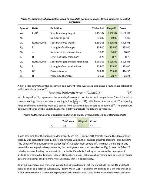
Table 18. Summary <strong>of</strong> parameters used to calculate parachute mass. Green indicates selected<br />
parachute.<br />
Symbol Units Definition Tri-Conical Ringsail Cross<br />
W C lb/ft 2 Specific canopy height 1.15E-02 1.15E-02 1.15E-02<br />
N G -- Number <strong>of</strong> gores 10.00 10.00 1.00<br />
w RT lb/ft/1000-lb Specific canopy weight 3.50E-03 3.50E-03 3.50E-03<br />
F RT lb Strength <strong>of</strong> radial tape 855.00 855.00 855.00<br />
N SL -- Number <strong>of</strong> suspension lines 10.00 10.00 10.00<br />
L S ft Length <strong>of</strong> suspension lines 8.76 8.76 8.76<br />
w SL lb/ft/1000-lb Specific weight <strong>of</strong> suspension lines 3.50E-03 3.50E-03 3.50E-03<br />
F SL lb Strength <strong>of</strong> suspension lines 855.00 855.00 855.00<br />
S 0 ft 2 Parachute Area 363.69 339.44 424.30<br />
D 0 ft Parachute Diameter 21.52 20.79 23.24<br />
A first order estimate <strong>of</strong> the parachute deployment force was calculated using a finite mass estimation<br />
in the following equation 16 .<br />
h te e e t e ( ) (37)<br />
In this equation, X 1 represents the opening-force-reduction factor and ranges from 0 to 1 based on<br />
canopy loading. Since the canopy loading is low ( ), this factor was set to 0.2.The opening<br />
force coefficient at infinite mass (C x ) comes from parachute data recorded in Table 19 16 . The parachute<br />
deployment force will be updated as higher fidelity parachute models are developed.<br />
Table 19.Opening force coefficients at infinite mass. Green indicates selected parachute.<br />
Tri-Conical Ringsail Cross<br />
C X 1.8 1.1 1.1<br />
It was assumed that the parachute deploys at Mach 0.8. Using a 3DOF trajectory code the deployment<br />
velocity was calculated to be 173 m/s. From these values, the resulting dynamic pressure (q) is 338.2 Pa<br />
(the density <strong>of</strong> the atmosphereis 0.0226 kg/m 3 at deployment condition). To meet the biological and<br />
material science payload requirements, the deployment load must stay below 40g. As seen in Table 17,<br />
this deployment loading remains within the limits. Parachute loading increases as the deployment<br />
altitude decreases due to an increase in atmospheric drag. <strong>Tech</strong>niques like reefing can be used to reduce<br />
parachute loading, but preliminary results show that is not necessary.<br />
To avoid supersonic and transonic instabilities, it was decided that the parachute for the 1U and 2x2U<br />
vehicles shall be deployed subsonically (below Mach 0.8). A deployment altitude <strong>of</strong> 5 km was chosen as<br />
it falls between the 3.1 km main deployment altitude <strong>of</strong> Stardust and 10 km main deployment altitude


