

SPORE Mission Design - Georgia Tech SSDL - Georgia Institute of ...
SPORE Mission Design - Georgia Tech SSDL - Georgia Institute of ...
SPORE Mission Design - Georgia Tech SSDL - Georgia Institute of ...

Create successful ePaper yourself
Turn your PDF publications into a flip-book with our unique Google optimized e-Paper software.
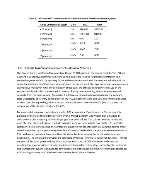
Table 8: LEO and GTO reference orbits defined in the Fixed coordinate system.<br />
Fixed Coordinate System Units LEO GTO<br />
X (Position) km 5765.00 -5407.30<br />
Y (Position) km -3931.80 3687.80<br />
Z (Position) km 0.00 0.00<br />
(Velocity)<br />
km/s -0.29 -4.82<br />
(Velocity)<br />
km/s -0.42 -7.06<br />
(Velocity)<br />
km/s 7.56 -4.90<br />
4.3 Deorbit Burn 2 (analysis completed by Matthew Nehrenz )<br />
The deorbit burn is performed by a constant thrust, 63 N thruster on the service module. The LEO and<br />
GTO orbits will follow a nominal trajectory using a trajectory tracking PD guidance controller. The<br />
nominal trajectory is built by applying thrust in the opposite direction <strong>of</strong> the vehicle’s velocity until the<br />
desired amount <strong>of</strong> delta-V has been attained; since the burn is short, this approach closely approximates<br />
an impulsive maneuver. After the completion <strong>of</strong> the burn, the attitude control system (ACS) on the<br />
service module will orient the vehicle for re-entry. Shortly before re-entry, the service module will<br />
separate from the entry vehicle. The goal <strong>of</strong> the following simulation is to characterize the vehicle’s<br />
state uncertainty at re-entry due to errors in the ACS, guidance system, and GPS. The two main sources<br />
<strong>of</strong> error contributing to the guidance system that are modeled here are the ACS (which controls the<br />
orientation <strong>of</strong> the thrust vector) and the GPS.<br />
For an on-orbit maneuver, a good estimate for ACS accuracy is a 1° pointing error. To see how this<br />
pointing error affects the guidance system error, a Matlab program was written that simulates an<br />
attitude controller operating within a larger guidance control loop. The control law used here is a PD<br />
controller that aligns a designated vehicle axis with some vector in vehicle coordinates. To apply this<br />
approach to trajectory tracking, the control law aligns the vehicle’s thruster axis with the desired thrust<br />
direction supplied by the guidance system. The ACS runs at 10 Hz while the guidance system operates at<br />
1 Hz; within each guidance time step, the attitude controller is keeping the thrust vector in proper<br />
orientation. The simulation uncouples the rotational dynamics from the translational dynamics—for the<br />
duration <strong>of</strong> the outer guidance loop, the attitude portion runs a 3 DOF simulation and saves the<br />
resulting thrust vector with error to be applied over that guidance time step. Uncoupling the rotational<br />
and translational dynamics allowed for easy application <strong>of</strong> the random attitude errors that produced an<br />
ACS pointing accuracy <strong>of</strong> 1°. Figure 6shows the simulation’s block diagram.


