

SPORE Mission Design - Georgia Tech SSDL - Georgia Institute of ...
SPORE Mission Design - Georgia Tech SSDL - Georgia Institute of ...
SPORE Mission Design - Georgia Tech SSDL - Georgia Institute of ...

Create successful ePaper yourself
Turn your PDF publications into a flip-book with our unique Google optimized e-Paper software.
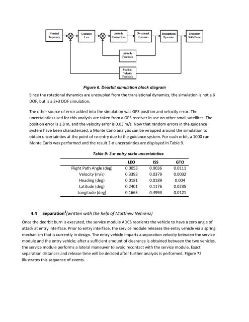
Figure 6. Deorbit simulation block diagram<br />
Since the rotational dynamics are uncoupled from the translational dynamics, the simulation is not a 6<br />
DOF, but is a 3+3 DOF simulation.<br />
The other source <strong>of</strong> error added into the simulation was GPS position and velocity error. The<br />
uncertainties used for this analysis are taken from a GPS receiver in use on other small satellites. The<br />
position error is 1.8 m, and the velocity error is 0.03 m/s. Now that random errors in the guidance<br />
system have been characterized, a Monte Carlo analysis can be wrapped around the simulation to<br />
obtain uncertainties at the point <strong>of</strong> re-entry due to the guidance system. For each orbit, a 1000 run<br />
Monte Carlo was performed and the result 3-σ uncertainties are displayed in Table 9.<br />
Table 9: 3-σ entry state uncertainties<br />
LEO ISS GTO<br />
Flight Path Angle (deg) 0.0053 0.0036 0.0111<br />
Velocity (m/s) 0.3393 0.0379 0.0032<br />
Heading (deg) 0.0181 0.0189 0.004<br />
Latitude (deg) 0.2401 0.1176 0.0235<br />
Longitude (deg) 0.1663 0.4993 0.0121<br />
4.4 Separation 2 (written with the help <strong>of</strong> Matthew Nehrenz)<br />
Once the deorbit burn is executed, the service module ADCS reorients the vehicle to have a zero angle <strong>of</strong><br />
attack at entry interface. Prior to entry interface, the service module releases the entry vehicle via a spring<br />
mechanism that is currently in design. The entry vehicle imparts a separation velocity between the service<br />
module and the entry vehicle; after a sufficient amount <strong>of</strong> clearance is obtained between the two vehicles,<br />
the service module performs a lateral maneuver to avoid recontact with the service module. Exact<br />
separation distances and release time will be decided after further analysis is performed. Figure 72<br />
illustrates this sequence <strong>of</strong> events.


