

SPORE Mission Design - Georgia Tech SSDL - Georgia Institute of ...
SPORE Mission Design - Georgia Tech SSDL - Georgia Institute of ...
SPORE Mission Design - Georgia Tech SSDL - Georgia Institute of ...

You also want an ePaper? Increase the reach of your titles
YUMPU automatically turns print PDFs into web optimized ePapers that Google loves.
Altitude, km<br />
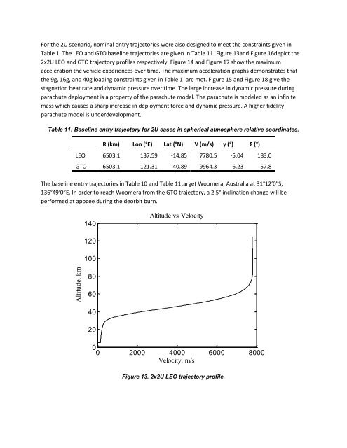
For the 2U scenario, nominal entry trajectories were also designed to meet the constraints given in<br />
Table 1. The LEO and GTO baseline trajectories are given in Table 11. Figure 13and Figure 16depict the<br />
2x2U LEO and GTO trajectory pr<strong>of</strong>iles respectively. Figure 14 and Figure 17 show the maximum<br />
acceleration the vehicle experiences over time. The maximum acceleration graphs demonstrates that<br />
the 9g, 16g, and 40g loading constraints given in Table 1 are met. Figure 15 and Figure 18 give the<br />
stagnation heat rate and dynamic pressure over time. The large increase in dynamic pressure during<br />
parachute deployment is a property <strong>of</strong> the parachute model. The parachute is modeled as an infinite<br />
mass which causes a sharp increase in deployment force and dynamic pressure. A higher fidelity<br />
parachute model is underdevelopment.<br />
Table 11: Baseline entry trajectory for 2U cases in spherical atmosphere relative coordinates.<br />
R (km) Lon (°E) Lat (°N) V (m/s) γ (°) Σ (°)<br />
LEO 6503.1 137.59 -14.85 7780.5 -5.04 183.0<br />
GTO 6503.1 121.31 -40.89 9964.3 -6.23 57.8<br />
The baseline entry trajectories in Table 10 and Table 11target Woomera, Australia at 31°12′0″S,<br />
136°49′0″E. In order to reach Woomera from the GTO trajectory, a 2.5° inclination change will be<br />
performed at apogee during the deorbit burn.<br />
140<br />
Altitude vs Velocity<br />
120<br />
100<br />
80<br />
60<br />
40<br />
20<br />
0<br />
0 2000 4000 6000 8000<br />
Velocity, m/s<br />
Figure 13. 2x2U LEO trajectory pr<strong>of</strong>ile.


