

SPORE Mission Design - Georgia Tech SSDL - Georgia Institute of ...
SPORE Mission Design - Georgia Tech SSDL - Georgia Institute of ...
SPORE Mission Design - Georgia Tech SSDL - Georgia Institute of ...

You also want an ePaper? Increase the reach of your titles
YUMPU automatically turns print PDFs into web optimized ePapers that Google loves.
Change in Peak Acceleration (Earth g's)<br />
Change in Impact Velocity (m/s)<br />
0.4<br />
0.35<br />
0.3<br />
0.25<br />
0.2<br />
0.15<br />
0.1<br />
0.05<br />
0<br />
-0.05<br />
-0.1<br />
-0.15<br />
Change in peak acceleration due<br />
to 3σ changes in inputs<br />
-3σ<br />
+3σ<br />
Change in impact velocity due to 3σ<br />
changes in inputs<br />
10<br />
5<br />
0<br />
-5<br />
-10<br />
-15<br />
-3σ<br />
+3σ<br />
Inputs<br />
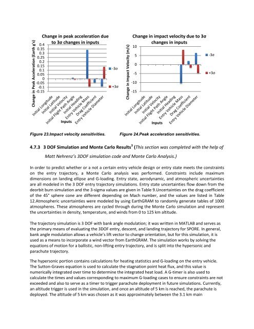
Figure 23.Impact velocity sensitivities.<br />
Inputs<br />
Figure 24.Peak acceleration sensitivities.<br />
4.7.3 3 DOF Simulation and Monte Carlo Results 3 (This section was completed with the help <strong>of</strong><br />
Matt Nehrenz’s 3DOF simulation code and Monte Carlo Analysis.)<br />
In order to predict whether or a not a certain entry vehicle design or entry state meets the constraints<br />
on the entry trajectory, a Monte Carlo analysis was performed. Constraints include maximum<br />
dimensions on landing ellipse and G-loading. Entry state, aerodynamic, and atmospheric uncertainties<br />
are all modeled in the 3 DOF entry trajectory simulations. Entry state uncertainties flow down from the<br />
deorbit burn simulation and the 3-sigma values are given in Table 9.Uncertainties on the drag coefficient<br />
<strong>of</strong> the 45° sphere cone are different depending on Mach number, and the values are listed in Table<br />
12.Atmospheric uncertainties were modeled by using EarthGRAM to randomly generate tables <strong>of</strong> 1000<br />
atmospheres. These atmospheres are cycled through during the Monte Carlo simulation and represent<br />
the uncertainties in density, temperature, and winds from 0 to 125 km altitude.<br />
The trajectory simulation is 3 DOF with bank angle modulation; it was written in MATLAB and serves as<br />
the primary means <strong>of</strong> evaluating the 3DOF entry, descent, and landing trajectory for <strong>SPORE</strong>. In general,<br />
bank angle modulation allows a vehicle’s lift vector to change orientation, but for this simulation, it is<br />
used as a means to incorporate a wind vector from EarthGRAM. The simulation works by solving the<br />
equations <strong>of</strong> motion for a ballistic, non-lifting entry trajectory, and is split into the hypersonic and<br />
parachute trajectory.<br />
The hypersonic portion contains calculations for heating statistics and G-loading on the entry vehicle.<br />
The Sutton-Graves equation is used to calculate the stagnation point heat flux, and this value is<br />
numerically integrated over time to determine the integrated heat load. A G-timer is also used to<br />
calculate the times and values corresponding to maximum G-loading cases to ensure constraints are not<br />
exceeded and also to serve as a timer to trigger parachute deployment in future simulations. Currently,<br />
an altitude trigger is used in the simulation, and once an altitude <strong>of</strong> 5 km is reached, the parachute is<br />
deployed. The altitude <strong>of</strong> 5 km was chosen as it was approximately between the 3.1 km main


