

SPORE Mission Design - Georgia Tech SSDL - Georgia Institute of ...
SPORE Mission Design - Georgia Tech SSDL - Georgia Institute of ...
SPORE Mission Design - Georgia Tech SSDL - Georgia Institute of ...

Create successful ePaper yourself
Turn your PDF publications into a flip-book with our unique Google optimized e-Paper software.
Number <strong>of</strong> Cases<br />
Number <strong>of</strong> Cases<br />
<strong>of</strong> the Hayabusa spacecraft8. At this altitude, the entry vehicle is traveling at a low subsonic speed at a<br />
near 90° flight path angle. In the future, a G-switch will be utilized to initiate parachute deployment at<br />
the desired deceleration level during atmospheric entry. The current Monte Carlo analysis was<br />
performed assuming an altitude trigger, but will be updated later to include a G-switch.<br />
4.9 Parachute Model<br />
A 3DOF parachute model was added to the 3 DOF and 6 DOF simulations. In the 3 DOF simulation, the<br />
parachute deployment occurs at an altitude <strong>of</strong> 5 km, but in the future will be modeled as a G-switch.<br />
Two types <strong>of</strong> inflation were modeled. For the Monte Carlo simulations, an instantaneous inflation was<br />
modeled to save on run time. For the nominal simulations, a linear inflation pr<strong>of</strong>ile was assumed using<br />
Knacke’s 3 inflation time relationship. Atmospheric wind contributions to the entry vehicle landing<br />
dispersions were modeled, assuming the parachute-vehicle system trimmed to the relative wind vector.<br />
In the POST model, the parachute was modeled as an increase in drag force according to Equation 38.<br />
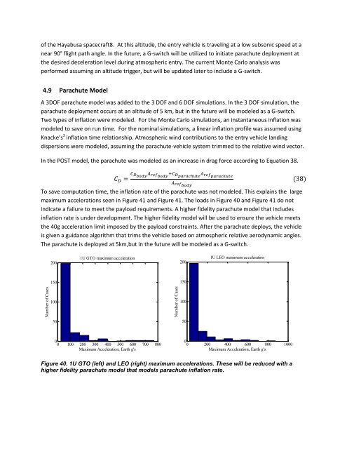
To save computation time, the inflation rate <strong>of</strong> the parachute was not modeled. This explains the large<br />
maximum accelerations seen in Figure 41 and Figure 41. The loads in Figure 40 and Figure 41 do not<br />
indicate a failure to meet the payload requirements. A higher fidelity parachute model that includes<br />
inflation rate is under development. The higher fidelity model will be used to ensure the vehicle meets<br />
the 40g acceleration limit imposed by the payload constraints. After the parachute deploys, the vehicle<br />
is given a guidance algorithm that trims the vehicle based on atmospheric relative aerodynamic angles.<br />
The parachute is deployed at 5km,but in the future will be modeled as a G-switch.<br />
(38)<br />
200<br />
1U GTO maximum acceleration<br />
200<br />
1U LEO maximum acceleration<br />
150<br />
150<br />
100<br />
100<br />
50<br />
50<br />
0<br />
0 100 200 300 400 500 600 700 800<br />
Maximum Acceleration, Earth g's<br />
0<br />
0 200 400 600 800 1000<br />
Maximum Acceleration, Earth g's<br />
Figure 40. 1U GTO (left) and LEO (right) maximum accelerations. These will be reduced with a<br />
higher fidelity parachute model that models parachute inflation rate.


