Snap-Action Switches Detection Switches General Catalogue 2005
Snap-Action Switches Detection Switches General Catalogue 2005
Snap-Action Switches Detection Switches General Catalogue 2005

You also want an ePaper? Increase the reach of your titles
YUMPU automatically turns print PDFs into web optimized ePapers that Google loves.
AV4<br />
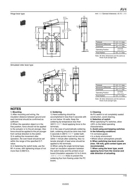
Hinge lever type mm inch <strong>General</strong> tolerance: ±0.15 ±.006<br />
5.1 4.55<br />
.201 .179<br />
3.0<br />
.118<br />
6.5<br />
.256<br />
(P.T.)<br />
2.4 max.<br />
.094<br />
(O.P.)<br />
6.4 ±0.6<br />
.252 ±.024<br />
(F.P.)<br />
9.0 max.<br />
.354<br />
0.11<br />
.004<br />
2.5<br />
.098<br />
0.8<br />
.031<br />
1.5<br />
.059<br />
3.1<br />
.122<br />
1.4<br />
.055<br />
1.4<br />
.055<br />
1.2<br />
.047<br />
4.0<br />
.157<br />
7.5<br />
.295<br />
0.8<br />
.031<br />
1.65 dia.<br />
.065<br />
0.6<br />
.024<br />
Pretravel<br />
Movement Differential<br />
Overtravel<br />
Operating Position<br />
Free Position<br />
2.4 .094 max.<br />
0.7 .028 max.<br />
0.4 .016 min.<br />
6.4±0.6<br />
.252±.024<br />
9.0 .354 max.<br />
Note: All other dimensions are the same as<br />
those of pin plunger type.<br />
Simulated roller lever type<br />
5.5<br />
.217<br />
3.0<br />
.118<br />
0.6 R<br />
.024 R<br />
(P.T.)<br />
2.2 max.<br />
.087<br />
0.11<br />
.004<br />
2.5<br />
.098<br />
0.8<br />
.031<br />
0.7<br />
.028<br />
(O.P.)<br />
6.7 ±0.5<br />
.264 ±.020<br />
1.65 dia.<br />
.065<br />
(F.P.)<br />
9.4 max.<br />
.370<br />
Pretravel<br />
Movement Differential<br />
Overtravel<br />
Operating Position<br />
Free Position<br />
2.2 .087 max.<br />
0.7 .028 max.<br />
0.3 .012 min.<br />
6.7±0.5<br />
.264±.020<br />
9.4 .370 max.<br />
Note: All other dimensions are the same as<br />
those of pin plunger type.<br />
NOTES<br />
1. Mounting<br />
1) After mounting and wiring, the<br />
insulation distance between ground and<br />
each terminal should be confirmed as<br />
sufficient.<br />
2) When the operation object is in the<br />
free position, force should not be applied<br />
to the actuator or to the pin plunger. Also<br />
force should be applied to the pin plunger<br />
from vertical direction to the switch.<br />
3) In setting the movement after<br />
operation, the over-travel should be set<br />
within the range of the specified O.T.<br />
value.<br />
4) In fastening the switch body, use the<br />
M1.4 screw, with tightening torque of not<br />
more than 0.098 N·m.<br />
2. Soldering<br />
1) Hand soldering should be<br />
accomplished in less than 5 seconds with<br />
an iron below 18 watts. Keep the<br />
soldering tip temperature less than<br />
320°C 608°F. Avoid applying force to the<br />
terminals.<br />
2) In the case of automatically soldering<br />
bath, soldering should be done less than<br />
5 seconds in 260°C 500°F solder bath.<br />
3) Terminal portion must not be moved<br />
within 1 minute after soldering. Also no<br />
tensile strength of lead wires should be<br />
applied to the terminals.<br />
4) When using the angle terminal type,<br />
insert an insulation separator between<br />
the switch body and the printed circuit<br />
board (Insulation separator 0.2 to 0.4mm<br />
.008 to .016 inch thick) to prevent the<br />
soldering flux from flowing under the PC<br />
board.<br />
3. Cleaning<br />
As FU switch is not completely sealed<br />
construction, avoid cleaning.<br />
4. Selection of switch<br />
When specifying FU switches, allow<br />
±20% to the listed operating<br />
characteristics.<br />
5. Avoid using and keeping switches<br />
in the following conditions:<br />
• In corrosive gases<br />
• In a dusty environment<br />
• Where silicon atmosphere prevails<br />
6. When switching low-level circuits<br />
(max. 100 mA), gold contact types are<br />
recommended.<br />
7. When using the lever type, avoid<br />
applying force from the reverse and<br />
side direction of actuating.<br />
113