Snap-Action Switches Detection Switches General Catalogue 2005
Snap-Action Switches Detection Switches General Catalogue 2005
Snap-Action Switches Detection Switches General Catalogue 2005

You also want an ePaper? Increase the reach of your titles
YUMPU automatically turns print PDFs into web optimized ePapers that Google loves.
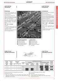
2. Right side hinge lever type<br />
AGL<br />
mm inch<br />
1.0 dia.<br />
.039 dia.<br />
4.8<br />
.189<br />
4.0<br />
.157<br />
26.4 ±0.15<br />
1.039 ±.006<br />
TTP 3.6 .142 max.<br />
O.P. 7.1 ±1.3 .280 ±.051<br />
F.P. 10.1 .398 max.<br />
12.5 ±0.15<br />
.492 ±.006<br />
5<br />
.197<br />
2.8 ±0.1<br />
.110 ±.004<br />
19.85<br />
.781<br />
15.35 ±0.15<br />
.604 ±.006<br />
2.4<br />
.094<br />
TTP 6.0 .236 max.<br />
O.P. 9.5 ±1.3 .374 ±.051<br />
F.P. 12.5 .492 max.<br />
21.2<br />
.835<br />
19.45 ±0.2<br />
.766 ±.008<br />
12.25<br />
.482<br />
5.8<br />
.228<br />
12.5 .492<br />
23.5 .925<br />
27.8 1.094<br />
34 1.339<br />
2.8 ±0.1<br />
.110 ±.004<br />
3.5<br />
.138<br />
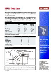
3. Left side hinge lever type<br />
F.P. 10.1 .398 max.<br />
O.P. 7.1 ±1.3 .280 ±.051<br />
TTP 3.6 .142 max.<br />
26.4 ±0.15<br />
1.039 ±.006 4.0<br />
.157<br />
1.0 dia.<br />
.039 dia.<br />
4.8<br />
.189<br />
12.5 ±0.15<br />
.492 ±.006<br />
5<br />
.197<br />
F.P. 12.5 .492 max.<br />
O.P. 9.5 ±1.3 .374 ±.051<br />
TTP 6.0 .236 max.<br />
2.4<br />
.094<br />
15.35 ±0.15<br />
.604 ±.006<br />
19.85<br />
.781<br />
21.2<br />
.835<br />
19.45 ±0.2<br />
.766 ±.008<br />
2.8 ±0.1<br />
.110 ±.004<br />
12.25<br />
.482<br />
5.8<br />
.228<br />
12.5 .492<br />
23.5 .925<br />
27.8 1.094<br />
34 1.339<br />
2.8 ±0.1<br />
.110 ±.004<br />
3.5<br />
.138<br />
NOTES<br />
1. A and B of the figure below are the<br />
additional terminals to fix the switch<br />
body on the PC board. Since these<br />
terminals are related No.1 terminal<br />
and No.2 terminal respectively, please<br />
be sure to maintain adequate<br />
insulating clearance between each<br />
terminal and ground.<br />
A<br />
No. 1 terminal<br />
B<br />
No. 2 terminal<br />
2. In setting the movement after<br />
operation, the over-travel should be<br />
set from 70% to 100%. Setting the<br />
movement less than 70% may cause<br />
degrading the electrical mechanical<br />
performance.<br />
3. Soldering operation<br />
Soldering must be done as quickly as<br />
possible.<br />
260°C 500°F: within 10 seconds<br />
350°C 662°F: within 3 seconds<br />
During the operation, care should be<br />
taken to prevent flux entrance inside the<br />
switch. The positioning tab may be<br />
changed in shape.<br />
4. Please pay attention to the<br />
insulation distance between terminals<br />
and between terminal and the ground<br />
after mounting and wiring.<br />
5. Environment<br />
Avoid the location nearby the conductive<br />
material which possibly attaches the<br />
switch.<br />
125