Snap-Action Switches Detection Switches General Catalogue 2005
Snap-Action Switches Detection Switches General Catalogue 2005
Snap-Action Switches Detection Switches General Catalogue 2005

You also want an ePaper? Increase the reach of your titles
YUMPU automatically turns print PDFs into web optimized ePapers that Google loves.
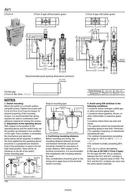
AV1<br />
3 Form A 3 Form A type without button guard<br />
3 Form A type with button guard<br />
18<br />
.709<br />
18<br />
.709<br />
51<br />
2.008<br />
8 dia.<br />
.315 dia.<br />
51<br />
2.008<br />
18<br />
8 dia. .709<br />
.315 dia.<br />
14<br />
.551<br />
6<br />
.236<br />
(F.P.) (T.T.P.)<br />
(O.P.)<br />
(F.P.) (T.T.P.)<br />
(O.P.)<br />
20.9<br />
.823<br />
50<br />
1.969<br />
47.8<br />
1.882<br />
2.1<br />
.083<br />
33.3<br />
1.311<br />
8<br />
.315<br />
50<br />
1.969<br />
47.8<br />
1.882<br />
2.1<br />
.083<br />
33.3<br />
1.311<br />
8<br />
.315<br />
15.2 ±0.8<br />
0.8<br />
7.6<br />
.598 ±.032 .031 .299<br />
.250 Q.C.<br />
7.6 0.8 6.35<br />
terminal<br />
.299 .031 .250<br />
30.4 ±0.8<br />
1.197 ±.032<br />
0.8<br />
.031<br />
10.6<br />
.417<br />
45.6 ±0.8<br />
13.8<br />
1.795 ±.032<br />
.543<br />
14.8<br />
.583<br />
Recommended panel opening dimensions (common)<br />
R1.3 max.<br />
R.051 max.<br />
15.2 ±0.8<br />
0.8<br />
7.6<br />
.598 ±.032 .031<br />
.299<br />
.250 Q.C.<br />
7.6 0.8 6.35<br />
terminal<br />
.299 .031 .250<br />
30.4 ±0.8<br />
1.197 ±.032<br />
45.6 ±0.8<br />
1.795 ±.032<br />
0.8<br />
.031<br />
10.6<br />
.417<br />
13.8<br />
.543<br />
14.8<br />
.583<br />
Contact gap<br />
3 Form A: Min. 8mm .315inch<br />
A<br />
15<br />
.591<br />
Panel thickness 1.0 .039 2.5 .098<br />
Dimension A 47.0 1.850 47.3 1.862<br />
NOTES<br />
1. Switch mounting<br />
Mount the switch to a smooth surface<br />
using M4 screws. Tighten the screws with<br />
0.3 to 0.5 N·m {3 to 5 kg·cm} torque. To<br />
prevent loosening of the mounting<br />
screws, it is recommended that spring<br />
washers be used in combination with<br />
adhesive material for locking the screws.<br />
2. Adjustment of the operating device:<br />
With respect to the position of the<br />
operating device and the switch body, set<br />
the position as indicated in the condition<br />
on the right. If this condition is exceeded,<br />
the mechanical and electrical<br />
performance will be impaired. In addition,<br />
the force applied by the operating device<br />
should be in a perpendicular direction.<br />
Even if the pushbutton is used in the full<br />
total travel position, there will be no<br />
influence on the life of the switch.<br />
Screw mounting type<br />
Operating<br />
device<br />
More than 17 mm<br />
.669 inch<br />
AV1<br />
switch<br />
Operating<br />
device<br />
10 to<br />
10.5 mm<br />
.394 to<br />
.413 inch<br />
AV1<br />
switch<br />
<strong>Snap</strong>-in mounting type<br />
Free condition<br />
Operating<br />
device<br />
More than<br />
14.5 mm<br />
.571 inch<br />
Operation condition<br />
7.5 to 8 mm<br />
.295 to<br />
.315 inch<br />
3. Confirming insulating distance:<br />
Before mounting and wiring, the<br />
insulating distance between terminals<br />
and between terminals and ground<br />
should be checked for assurance of<br />
proper distance. With respect to the<br />
terminal connections, it is recommended<br />
that receptacles with insulating sleeves<br />
be used.<br />
Also, consideration should be given to the<br />
wiring not to apply force to the terminal<br />
section normally.<br />
4. Avoid using GW switches in the<br />
following conditions:<br />
• Locations where hydrogen sulfide gas<br />
or other corrosive gases exist.<br />
• Locations where gasoline, thinner, or<br />
other inflammable or explosive gases<br />
exist.<br />
• Locations where there are dust and<br />
refuse.<br />
• For operation where the perpendicular<br />
operating speed is less than 10mm/sec.<br />
• For operation frequency of make/break<br />
exceeding 60 cpm.<br />
• For ambient temperatures exceeding<br />
the range of –25°C to +85°C +13°F to<br />
+185°F.<br />
• For ambient humidity exceeding 85%<br />
R.H.<br />
• For use in a silicon atmosphere.<br />
5. For use of AV1405 (1 Form Z type):<br />
For the type AV1405, the air distance<br />
between the N.O. and N.C. contacts is<br />
less than the required value of VDE. The<br />
N.O. and the N.C. contacts can carry only<br />
the same electric potential.<br />
Free condition<br />
Operation condition<br />
122