Snap-Action Switches Detection Switches General Catalogue 2005
Snap-Action Switches Detection Switches General Catalogue 2005
Snap-Action Switches Detection Switches General Catalogue 2005

You also want an ePaper? Increase the reach of your titles
YUMPU automatically turns print PDFs into web optimized ePapers that Google loves.
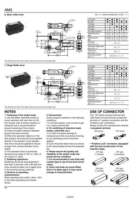
AM5<br />
6. Short roller lever mm inch <strong>General</strong> tolerance: ±0.25 ±.010<br />
The dimensions other than drawn above are same as pin plunger type.<br />
1.55 dia.<br />
0.1A type — —<br />
.061<br />
6A type <br />
11A type — — — —<br />
6.4<br />
.252<br />
16A type — — <br />
3.2 4.75<br />
21A type — — — <br />
(P.T.)<br />
.126 .187<br />
20.6 ±0.5<br />
±.020<br />
4.9<br />
1.6 max.<br />
.811 1.8 6.35<br />
7th digit of part No. 3 4 5 6 7<br />
.193<br />
.063<br />
27.8 1.094 .071 .250<br />
Operating force,<br />
0.59 1.08 2.16 3.14 4.12<br />
20.2 .795 2.8<br />
Max.<br />
N N N N N<br />
.110<br />
+0.25<br />
4.8<br />
3.1 –0.05 dia.<br />
+.010<br />
.189 Release force,<br />
0.098 0.20 0.39 0.59 0.78<br />
.122 –.002 dia.<br />
(O.P.)<br />
Min.<br />
N N N N N<br />
4.1<br />
±0.5<br />
20.7<br />
5.65<br />
.161<br />
.815<br />
.222<br />
Pretravel,<br />
±.020<br />
15.9 10.3 ±0.1<br />
NC<br />
1.6 .063<br />
0.5 9.3 6.5<br />
max. mm inch<br />
.626 .406 ±.004<br />
2<br />
1<br />
.020 .366 .256<br />
NO<br />
3<br />
Movement differential,<br />
C<br />
6.65<br />
0.5 .020<br />
±0.15<br />
2.8 3.4<br />
.262<br />
max. mm inch<br />
.110 .134 ±.006 13.5<br />
Overtravel,<br />
+0.25<br />
±0.1<br />
3.1<br />
10.3<br />
–0.05 22.2 .531<br />
0.9 .035<br />
+.010<br />
.122<br />
.406 min. mm inch<br />
–.002 .874 ±.004 39.45<br />
Operating position<br />
1.553<br />
20.7±0.5 .815±.020<br />
mm inch<br />
7. Hinge Roller lever<br />
1.55 dia.<br />
0.1A type — —<br />
.061<br />
6A type <br />
6.4<br />
11A type — — — —<br />
.252<br />
16A type — — <br />
3.2 4.75<br />
21A type — — — <br />
(P.T.)<br />
.126 .187<br />
34.2<br />
3.2 max.<br />
±0.5<br />
6.35<br />
±.020<br />
1.346<br />
4.9 7th digit of part No. 3 4 5 6 7<br />
.126<br />
1.8 .250<br />
.193<br />
27.8 1.094 .071<br />
Operating force,<br />
0.29 0.59 1.18 1.77 2.35<br />
20.2 .795 2.8<br />
4.8 Max.<br />
N N N N N<br />
+0.25<br />
.110 3.1 –0.05 dia.<br />
.189<br />
+.010<br />
.122 –.002 dia.<br />
Release force,<br />
0.049 0.098 0.20 0.29 0.39<br />
(O.P.)<br />
4.1<br />
Min.<br />
N N N N N<br />
±1.0<br />
20.7<br />
5.65<br />
.161<br />
.815<br />
.222<br />
Pretravel,<br />
±.039<br />
15.9 10.3 ±0.1<br />
NC<br />
0.5 9.3 6.5<br />
3.2 .126<br />
.626 .406 ±.004<br />
2<br />
max. mm inch<br />
1<br />
.020 .366 .256<br />
NO<br />
3<br />
C<br />
6.65<br />
Movement differential,<br />
1.0 .039<br />
±0.15<br />
2.8 3.4<br />
.262<br />
max. mm inch<br />
.110 .134 ±.006 13.5<br />
+0.25<br />
±0.1<br />
3.1<br />
10.3<br />
–0.05 22.2 .531<br />
Overtravel,<br />
1.4 .055<br />
+.010<br />
.122<br />
.406<br />
–.002 .874 min. mm inch<br />
±.004<br />
39.45<br />
Operating position<br />
1.553<br />
20.7±1.0 .815±.039<br />
mm inch<br />
The dimensions other than drawn above are same as pin plunger type.<br />
NOTES<br />
1. Fastening of the switch body<br />
1) Use flat filister head M3 screws to<br />
mount switches with less than a 0.49<br />
N·m torque. Use of screws washers or<br />
adhesive lock is recommended to<br />
prevent loosening of the screws.<br />
2) Check insulation distance between<br />
ground and each terminal.<br />
3) When the operation object is in the<br />
free position, force should not be applied<br />
directly to the actuator or pin plunger.<br />
Also force should be applied to the pin<br />
plunger from vertical direction to the<br />
switch.<br />
4) The standard value of overtravel<br />
should be the range of 70% to 100% of<br />
the rated O.T. value.<br />
2. Soldering operations<br />
Soldering should be accomplished in<br />
less than 5 seconds, with a 60 watt iron.<br />
Care should be taken not to apply force<br />
to the terminal during soldering.<br />
3. Varience of operating<br />
characteristics<br />
When specifying the switch, allow +20%<br />
to the listed operating and release<br />
forces.<br />
4. Environment<br />
Avoid using the switches in the following<br />
conditions;<br />
• In corrosive gases, such as silicon gas<br />
• In a dusty environment<br />
5. For switching of inductive loads<br />
(relays, solenoids, etc.)<br />
1) In order to prevent damage to<br />
contacts due to the occurrence of arcing,<br />
an arc absorbing circuit should be<br />
applied.<br />
2) Care should be taken that occurrence<br />
in AC load possibly shorten the expected<br />
life.<br />
6. Please assure the quality and<br />
reliability of the switch under the<br />
actual service condition.<br />
7. It is recommended to use Gold clad<br />
contact type in use of low-level circuit<br />
rating.<br />
8. Cover and body are press-fitted.<br />
Once it is taken apart, it may cause<br />
change of characteristics.<br />
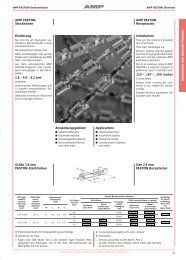
USE OF CONNECTOR<br />
The .187 Quick-connect terminal and<br />
.250 Quick-connect terminal accept the<br />
all kinds of 1 polarity connectors and the<br />
“Positive Lock” connectors.<br />
Please contact the manufacturers directly.<br />
• receptacle terminal<br />
.250 series .187 series<br />
• “Positive Lock” connector. (equipped<br />
with the lock construction of low<br />
insertion type)<br />
.187 type<br />
(1 polarity)<br />
.250 type<br />
(1 polarity)<br />
.187 type<br />
(2 polarities)<br />
.187 type<br />
(3 polarities)<br />
72