Snap-Action Switches Detection Switches General Catalogue 2005
Snap-Action Switches Detection Switches General Catalogue 2005
Snap-Action Switches Detection Switches General Catalogue 2005

You also want an ePaper? Increase the reach of your titles
YUMPU automatically turns print PDFs into web optimized ePapers that Google loves.
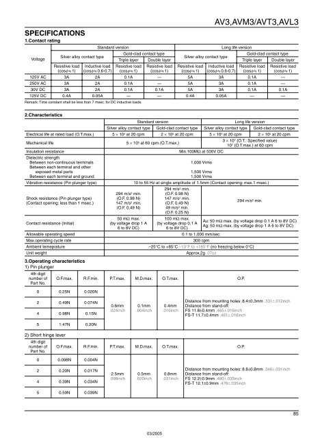
SPECIFICATIONS<br />
1.Contact rating<br />
Voltage<br />
Silver alloy contact type<br />
Resistive load<br />
(cosφ]1)<br />
Standard version<br />
Inductive load<br />
(cosφ]0.6-0.7)<br />
Remark: Time constant shall be less than 7 msec. for DC inductive loads.<br />
AV3,AVM3/AVT3,AVL3<br />
Long life version<br />
Gold-clad contact type<br />
Gold-clad contact type<br />
Silver alloy contact type<br />
Triple layer Double layer Triple layer Double layer<br />
Resistive load<br />
(cosφ]1)<br />
Resistive load<br />
(cosφ]1)<br />
Resistive load<br />
(cosφ]1)<br />
Inductive load<br />
(cosφ]0.6-0.7)<br />
Resistive load<br />
(cosφ]1)<br />
Resistive load<br />
(cosφ]1)<br />
125V AC 3A 2A 0.1A — 5A 3A 0.1A —<br />
250V AC 3A 2A 0.1A — 5A 3A 0.1A —<br />
30V DC 3A 2A 0.1A 0.1A 5A 3A 0.1A 0.1A<br />
125V DC 0.4A 0.05A — — 0.4A 0.05A — —<br />
2.Characteristics<br />
Standard version<br />
Long life version<br />
Silver alloy contact type Gold-clad contact type Silver alloy contact type Gold-clad contact type<br />
Electrical life at rated load (O.T.max.) 5 × 10 4 at 20 cpm 2 × 10 5 at 20 cpm 5 × 10 4 at 20 cpm 2 × 10 5 at 20 cpm<br />
Mechanical life<br />
5 × 10 5 at 60 cpm (O.T.max.)<br />
3 × 10 7 (O.T.: Specified value)<br />
10 7 (O.T.max.) at 60 cpm<br />
Insulation resistance<br />
Min.100MΩ at 500V DC<br />
Dielectric strength<br />
Between non-continuous terminals<br />
Between each terminal and other<br />
exposed metal parts<br />
Between each terminal and ground<br />
Vibration resistance (Pin plunger type)<br />
Shock resistance (Pin plunger type)<br />
(Contact opening: less than 1 msec.)<br />
Contact resistance (Initial)<br />
Allowable operating speed<br />
Max.operating cycle rate<br />
Ambient temeprature<br />
Unit weight<br />
294 m/s 2 min.<br />
(O.F. 0.98 N)<br />
147 m/s 2 min.<br />
(O.F. 0.49 N)<br />
50 mΩ max.<br />
(by voltage drop 1 A<br />
6 to 8V DC)<br />
1,000 Vrms<br />
1,500 Vrms<br />
1,500 Vrms<br />
10 to 55 Hz at single amplitude of 1.5mm (Contact opening: max.1 msec.)<br />
294 m/s 2 min.<br />
(O.F. 0.98 N)<br />
147 m/s 2 min.<br />
(O.F. 0.49 N)<br />
49 m/s 2 min.<br />
(O.F. 0.25 N)<br />
100 mΩ max.<br />
(by voltage drop 0.1 A<br />
6 to 8V DC)<br />
3.Operating characteristics<br />
1) Pin plunger<br />
4th digit<br />
number of O.F.max. R.F.min. P.T.max. M.D.max. O.T.max. O.P.<br />
Part No.<br />
0 0.25N 0.020N<br />
294 m/s 2 min.<br />
Au: 50 mΩ max. (by voltage drop 0.1 A 6 to 8V DC)<br />
Ag: 50 mΩ max. (by voltage drop 1 A 6 to 8V DC)<br />
0.1 to 1,000 mm/sec.<br />
300 cpm<br />
–25°C to +85°C –13°F to +185°F (no freezing below 0°C)<br />
Approx.2g .07oz<br />
2 0.49N 0.074N<br />
4 0.98N 0.15N<br />
0.6mm<br />
.024inch<br />
0.1mm<br />
.004inch<br />
0.4mm<br />
.016inch<br />
Distance from mounting holes: 8.4±0.3mm .331±.012inch<br />
Distance from stand-off:<br />
FS 11.8±0.4mm .465±.016inch<br />
FS-T 11.7±0.4mm .461±.016inch<br />
5 1.47N 0.20N<br />
2) Short hinge lever<br />
4th digit<br />
number of O.F.max. R.F.min. P.T.max. M.D.max. O.T.max. O.P.<br />
Part No.<br />
0 0.098N 0.004N<br />
2 0.20N 0.017N<br />
4 0.39N 0.034N<br />
2.5mm<br />
.098inch<br />
0.5mm<br />
.020inch<br />
0.8mm<br />
.031inch<br />
Distance from mounting holes: 8.8±0.8mm .346±.031inch<br />
Distance from stand-off:<br />
FS 12.2±0.9mm .480±.035inch<br />
FS-T 12.1±0.9mm .476±.035inch<br />
5 0.59N 0.039N<br />
85