Snap-Action Switches Detection Switches General Catalogue 2005
Snap-Action Switches Detection Switches General Catalogue 2005
Snap-Action Switches Detection Switches General Catalogue 2005

You also want an ePaper? Increase the reach of your titles
YUMPU automatically turns print PDFs into web optimized ePapers that Google loves.
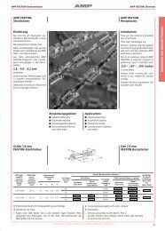
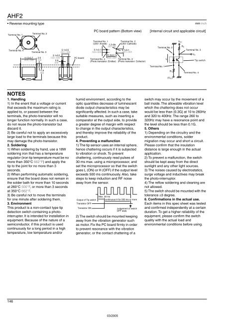
AHF2<br />
• Reverse mounting type<br />
mm inch<br />
Terminal No. 1<br />
Terminal No. 2<br />
PC board pattern (Bottom view)<br />
[Internal circuit and applicable circuit]<br />
Terminal No. 4<br />
11.5±0.7<br />
.453±.028<br />
5.1±0.5<br />
.201±.020<br />
3.1±0.5<br />
2.6 .122±.020<br />
.102 0.9<br />
.035<br />
Terminal No. 3<br />
PC board<br />
Terminal No. 1<br />
(LED: Anode) 1.3 dia.<br />
.051 dia.<br />
3.1±0.1<br />
.122±.004<br />
11.9±0.1<br />
.469±.004<br />
Terminal No. 4<br />
(Photo transistor: Emitter)<br />
Terminal No. 2<br />
(LED: Cathode)<br />
5.1±0.1<br />
.201±.004<br />
Terminal No. 3<br />
(Photo transistor: Collector)<br />
Terminal No. 1<br />
Terminal No. 2<br />
I F<br />
R 1<br />
(V CC )<br />
V CC<br />
R 2<br />
Terminal No. 3<br />
V O<br />
Tip switch<br />
11.9<br />
.469<br />
Terminal No. 4<br />
NOTES<br />
1. Handling<br />
1) In the enent that a voltage or current<br />
that exceeds the maximum rating is<br />
applied to, or passed between the<br />
terminals, the photo-transistor will no<br />
longer function normally. In such a case,<br />
do not reuse the photo-transistor but<br />
discard it.<br />
2) Be careful not to apply an excessively<br />
large load to the terminals because this<br />
may damage the photo-transistor.<br />
2. Soldering<br />
1) When soldering by hand, use a 18W<br />
soldering iron that has a temperature<br />
regulator (iron tip temperature must be no<br />
more than 350°C 662°F) and apply the<br />
tip to the joint for no more than 3<br />
seconds.<br />
2) When performing automatic soldering,<br />
ensure that the board does not remain in<br />
the solder bath for more than 10 seconds<br />
at 260°C 500°F, or more than 3 seconds<br />
at 350°C 662°F.<br />
3) Be careful not to move the terminals<br />
for one minute after soldering them.<br />
3. Environment<br />
This product is a non-contact type tip<br />
detection switch containing a photointerrupter.<br />
It is intended for installation in<br />
equipment. Because of the nature of a<br />
semiconductor, if this product is used<br />
continuously for a long period in a high<br />
temperature, low temperature and/or<br />
humid environment, according to the<br />
optic quantities decrease of luminescent<br />
diode output characteristics may be<br />
significantly affected. In such a case, take<br />
suitable measures, such as inserting a<br />
comparator at the output side, to provide<br />
a greater degree of margin with respect<br />
to change in the output characteristics,<br />
and thereby improve the reliability of the<br />
product.<br />
4. Preventing a malfunction<br />
1) The tip sensor uses an internal sphere,<br />
hence chattering occurs if it is subjected<br />
to vibration or shock. To prevent<br />
chattering, continuously read pulses of<br />
30 ms max. using a microprocessor, and<br />
set the microprocessor so that the switch<br />
goes L (ON) or H (OFF) if the output level<br />
exceeds 500 ms continuously. Also, take<br />
steps to keep induction and RF noise<br />
away from the sensor.<br />
Output of Tip switch<br />
Transistor OFF<br />
Transistor ON<br />
Max. 30 ms<br />
continuous H for 500 ms or more<br />
Judgement of switch<br />
OFF state<br />
2) The switch should be mounted keeping<br />
away from the vibration generator such<br />
as motor. Fix the PC board firmly in order<br />
to prevent resonance with the vibration<br />
generator, or the contact chattering of a<br />
switch may occur by the movement of a<br />
ball inside. The allowable vibration level<br />
which the chattering does not occur<br />
would be less than {0.3G} at 10 to 260Hz<br />
and 320 to 400Hz. The range 260 to<br />
320Hz may have a resonance point and<br />
the level should be less than 0.1G.<br />
5. Others<br />
1) Depending on the circuitry and the<br />
environmental conditions, solder<br />
migration may occur and short a circuit.<br />
Please confirm that the insulation<br />
distance is large enough in the actual<br />
application.<br />
2) To prevent a malfunction, the switch<br />
should be kept away from the direct<br />
sunlight and any other light sources.<br />
3) The noises caused by electrostatics,<br />
surge voltage and inductives may break<br />
the photo-interruptor.<br />
4) The reflow soldering and cleaning are<br />
not allowed.<br />
5) The switch should be mounted with the<br />
tolerance ±3 degree.<br />
6. Confirmations in the actual use.<br />
Each items in this spec sheet was tested<br />
and confirmed independently at a certain<br />
duration. To get a higher reliability of the<br />
equipment, please confirm the switch<br />
quality with the actual load and<br />
environmental conditions before using.<br />
146