Snap-Action Switches Detection Switches General Catalogue 2005
Snap-Action Switches Detection Switches General Catalogue 2005
Snap-Action Switches Detection Switches General Catalogue 2005

Create successful ePaper yourself
Turn your PDF publications into a flip-book with our unique Google optimized e-Paper software.
ABC2<br />
NOTES<br />
1. Mounting<br />
1) The positioning of the switch should be<br />
such that the pushbutton for the switch<br />
should not directly apply force to the<br />
operating section in the free condition.<br />
2) During both mounting and operation,<br />
care must be taken to protect the<br />
pushbutton from excessive stress, as this<br />
may cause malfunctioning.<br />
3) During mounting, the insulation<br />
distance between ground and each<br />
terminals should be confirmed as<br />
sufficient.<br />
2. Soldering<br />
1) For manual soldering; Iron tip<br />
temperature max. is 320°C 608°F and<br />
soldering should be completed within 3<br />
seconds.<br />
2) For reflow soldering; Perform soldering<br />
reflow at a peak surface temperature of<br />
the PC board not to exceed 245°C 473°F.<br />
3) For cream soldering; Screen thickness<br />
is recommended between 0.10 to 0.15<br />
mm .004 to .006 inch.<br />
4) During soldering, care should be taken<br />
not to apply excessive stress to the<br />
terminals as the resulting deformation<br />
may cause malfunction.<br />
5) Excessively high solder tab<br />
temperature and soldering iron wattage<br />
should also be avoided as these factors<br />
may harm switching performance.<br />
6) As this switch is thin, using flux should<br />
be avoided for the reason of the flux may<br />
come inside of the switch and cause<br />
damage.<br />
3. Switch operations<br />
1) The installation position of the<br />
activating unit that operates the switch<br />
should be set at a distance of 1.4 to 1.9<br />
mm .055 to .075 inch from the center of<br />
the positioning projection for the type with<br />
boss (1.8 to 2.6 mm .071 to .102 inch for<br />
long stroke type) and at a distance of 3.5<br />
to 4.0 mm .138 to .157 inch from the<br />
bottom for the low profile type without<br />
(3.9 to 4.7 mm .154 to .185 inch for long<br />
stroke type).<br />
2) For 1 Form B contact type operation,<br />
set the pushbutton so it returns to the<br />
free position.<br />
3) Avoid using the switch as a stopper<br />
since it may cause trouble with the<br />
operations.<br />
4) When using the switch to operate in<br />
the sideways direction, ensure that the<br />
corner roundness of the operating unit is<br />
more than R1.<br />
4. Environment<br />
1) These switches do not have a sealed<br />
construction. As such, the construction of<br />
the equipment in which the switches are<br />
to be installed should be given careful<br />
consideration when the switches are to<br />
be used in locations where corrosive<br />
gases, silicon or other substances which<br />
will adversely affect the contacts are<br />
used, where there is a high concentration<br />
of dust or where the switches may be<br />
exposed to condensation or water. Using<br />
switches in locations like these may<br />
cause malfunctioning.<br />
2) Avoid using this switch in hightemperature,<br />
high-humidity or<br />
condensation-forming environments and<br />
avoid allowing droplets of water to remain<br />
on the switch or come into contact with it.<br />
These conditions may interfere with the<br />
performance of the switch (resulting in<br />
short-circuiting, etc.). Use the type with<br />
the gold contacts in applications involving<br />
trains, aircraft, motor vehicles or medical<br />
equipment where the switch must satisfy<br />
safety and high reliability requirements.<br />
Please consult with us for the<br />
applications required high reliability.<br />
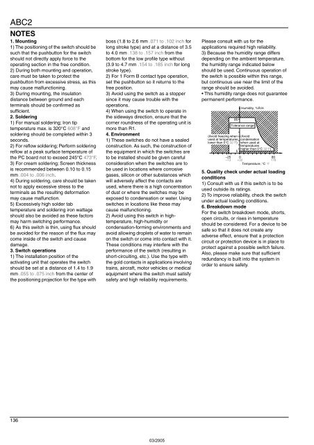
3) Because the humidity range differs<br />
depending on the ambient temperature,<br />
the humidity range indicated below<br />
should be used. Continuous operation of<br />
the switch is possible within this range,<br />
but continuous use near the limit of the<br />
range should be avoided.<br />
• This humidity range does not guarantee<br />
permanent performance.<br />
;;;<br />
;<br />
;;;;;<br />
;;;;;;;<br />
;;;;;;;;;<br />
;;;;;;;;;;<br />
;;;;;;;;;;<br />
;;;;;;;;;<br />
;;;;;;;;<br />
;;;;;;<br />
;;;;<br />
;;<br />
85<br />
Humidity, %R.H.<br />
Tolerance range<br />
(Avoid freezing when (Avoid<br />
used at temperatures condensation<br />
lower than 0°C 32°F) when used at<br />
temperatures<br />
5<br />
higher than 0°C 32°F)<br />
–25 0<br />
80<br />
–13 +32<br />
176<br />
Temperature, °C °F<br />
5. Quality check under actual loading<br />
conditions<br />
1) Consult with us if this switch is to be<br />
used outside its ratings.<br />
2) To improve reliability, check the switch<br />
under actual loading conditions.<br />
6. Breakdown mode<br />
For the switch breakdown mode, shorts,<br />
open circuits, or rises in temperature<br />
should be considered. For a device to be<br />
safe so that it does not create any<br />
adverse effect, ensure that a protection<br />
circuit or protection device is in place to<br />
protect against a possible switch failure.<br />
Also, please make sure that sufficient<br />
redundancy is built into the system in<br />
order to ensure safety.<br />
136