Snap-Action Switches Detection Switches General Catalogue 2005
Snap-Action Switches Detection Switches General Catalogue 2005
Snap-Action Switches Detection Switches General Catalogue 2005

Create successful ePaper yourself
Turn your PDF publications into a flip-book with our unique Google optimized e-Paper software.
ABC1<br />
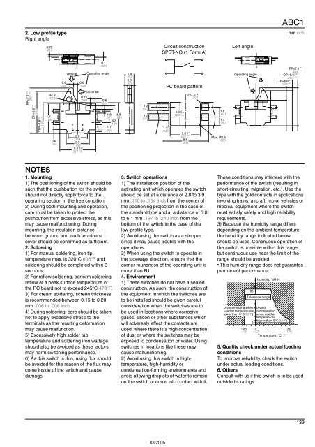
2. Low profile type<br />
Right angle<br />
mm inch<br />
0.25<br />
.010<br />
Circuit construction<br />
SPST-NO (1 Form A)<br />
Left angle<br />
.280 ±.008<br />
FP=7.1 ±0.2<br />
OP=6.6 ±0.3<br />
.260 ±.012<br />
TTP=4.8 ±0.2<br />
.189 ±.008<br />
R4.3<br />
R.169<br />
4.7<br />
.185<br />
0.6<br />
.024<br />
0.6<br />
.024<br />
Vertical<br />
2.9<br />
.114<br />
3.5<br />
.138<br />
5.5 −0.1<br />
.217<br />
0.6<br />
.024<br />
0.75<br />
.030<br />
+0.08<br />
+.003<br />
−.004<br />
0.1<br />
.004<br />
Operating angle<br />
Horizontal<br />
1.1<br />
.043<br />
0.6<br />
.024<br />
1.8 4.8<br />
.071 .189<br />
4.3<br />
.169<br />
1.7<br />
.067<br />
1.4<br />
.055<br />
0.5<br />
.020<br />
1.2<br />
.047<br />
1.2<br />
.047<br />
1.2<br />
.047<br />
PC board pattern<br />
4.3<br />
.169<br />
+0<br />
−0.15<br />
+0<br />
−.006<br />
+0.2<br />
5.6 0<br />
+.008<br />
.220 0<br />
8.5<br />
.335<br />
2-C 0.2<br />
.008<br />
1.8<br />
.071<br />
1.7<br />
.067<br />
Max. R0.5<br />
.020<br />
Operating angle<br />
FP=7.1 ±0.2<br />
.280 ±.008<br />
OP=6.6 ±0.3<br />
.260 ±.012<br />
TTP=4.8 ±0.2<br />
.189 ±.008<br />
NOTES<br />
1. Mounting<br />
1) The positioning of the switch should be<br />
such that the pushbutton for the switch<br />
should not directly apply force to the<br />
operating section in the free condition.<br />
2) During both mounting and operation,<br />
care must be taken to protect the<br />
pushbutton from excessive stress, as this<br />
may cause malfunctioning. During<br />
mounting, the insulation distance<br />
between ground and each terminals/<br />
cover should be confirmed as sufficient.<br />
2. Soldering<br />
1) For manual soldering, iron tip<br />
temperature max. is 320°C 608°F and<br />
soldering should be completed within 3<br />
seconds.<br />
2) For reflow soldering, perform soldering<br />
reflow at a peak surface temperature of<br />
the PC board not to exceed 245°C 473°F.<br />
3) For cream soldering, screen thickness<br />
is recommended between 0.15 to 0.20<br />
mm .006 to .008 inch.<br />
4) During soldering, care should be taken<br />
not to apply excessive stress to the<br />
terminals as the resulting deformation<br />
may cause malfunction.<br />
5) Excessively high solder tab<br />
temperature and soldering iron wattage<br />
should also be avoided as these factors<br />
may harm switching performance.<br />
6) As this switch is thin, using flux should<br />
be avoided for the reason of the flux may<br />
come inside of the switch and cause<br />
damage.<br />
3. Switch operations<br />
1) The installation position of the<br />
activating unit which operates the switch<br />
should be set at a distance of 2.8 to 3.9<br />
mm .110 to .154 inch from the center of<br />
the positioning projection in the case of<br />
the standard type and at a distance of 5.0<br />
to 6.1 mm .197 to .240 inch from the<br />
bottom of the switch in the case of the<br />
low-profile type.<br />
2) Avoid using the switch as a stopper<br />
since it may cause trouble with the<br />
operations.<br />
3) When using the switch to operate in<br />
the sideways direction, ensure that the<br />
corner roundness of the operating unit is<br />
more than R1.<br />
4. Environment<br />
1) These switches do not have a sealed<br />
construction. As such, the construction of<br />
the equipment in which the switches are<br />
to be installed should be given careful<br />
consideration when the switches are to<br />
be used in locations where corrosive<br />
gases, silicon or other substances which<br />
will adversely affect the contacts are<br />
used, where there is a high concentration<br />
of dust or where the switches may be<br />
exposed to condensation or water. Using<br />
switches in locations like these may<br />
cause malfunctioning.<br />
2) Avoid using this switch in hightemperature,<br />
high-humidity or<br />
condensation-forming environments and<br />
avoid allowing droplets of water to remain<br />
on the switch or come into contact with it.<br />
These conditions may interfere with the<br />
performance of the switch (resulting in<br />
short-circuiting, migration, etc.). Use the<br />
type with the gold contacts in applications<br />
involving trains, aircraft, motor vehicles or<br />
medical equipment where the switch<br />
must satisfy safety and high reliability<br />
requirements.<br />
3) Because the humidity range differs<br />
depending on the ambient temperature,<br />
the humidity range indicated below<br />
should be used. Continuous operation of<br />
the switch is possible within this range,<br />
but continuous use near the limit of the<br />
range should be avoided.<br />
• This humidity range does not guarantee<br />
permanent performance.<br />
;;;<br />
;<br />
;;;;;<br />
;;;;;;;<br />
;;;;;;;;;<br />
;;;;;;;;;;<br />
;;;;;;;;;;<br />
;;;;;;;;;<br />
;;;;;;;;<br />
;;;;;;<br />
;;;;<br />
;;<br />
85<br />
Humidity, %R.H.<br />
Tolerance range<br />
(Avoid freezing when (Avoid<br />
used at temperatures condensation<br />
lower than 0°C 32°F) when used at<br />
temperatures<br />
5<br />
higher than 0°C 32°F)<br />
–25 0<br />
80<br />
–13 +32<br />
176<br />
Temperature, °C °F<br />
5. Quality check under actual loading<br />
conditions<br />
To improve reliability, check the switch<br />
under actual loading conditions.<br />
6. Others<br />
Consult with us if this switch is to be used<br />
outside its ratings.<br />
139