Snap-Action Switches Detection Switches General Catalogue 2005
Snap-Action Switches Detection Switches General Catalogue 2005
Snap-Action Switches Detection Switches General Catalogue 2005

You also want an ePaper? Increase the reach of your titles
YUMPU automatically turns print PDFs into web optimized ePapers that Google loves.
ABC3<br />
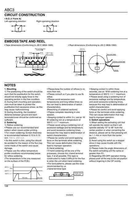
CIRCUIT CONSTRUCTION<br />
• N.O. (1 Form A)<br />
Left operating direction<br />
Right operating direction<br />
EMBOSS TAPE AND REEL<br />
• Tape dimensions (Conforming to JIS C 0806-1995) • Reel dimensions (Conforming to JIS C 0806-1995)<br />
1.75<br />
.069<br />
(4.0)<br />
(.157)<br />
Pull-out direction<br />
(2.0)<br />
(.079)<br />
1.55 ±0.05 dia.<br />
.061 ±.002 dia.<br />
+2<br />
(16.4 0 )<br />
+.079<br />
(.646 )<br />
0<br />
Top cover tape<br />
7.8<br />
16.0 .307<br />
.630<br />
P E T<br />
(370 dia.)<br />
(14.567 dia.)<br />
Emboss carrier tape<br />
12.0<br />
.472<br />
12.0<br />
.472<br />
Cavity<br />
(22)<br />
(.866)<br />
NOTES<br />
1. Mounting<br />
1) The positioning of the switch should be<br />
such that the pushbutton for the switch<br />
should not directly apply force to the<br />
operating section in the free condition.<br />
2) During both mounting and operation,<br />
care must be taken to protect the<br />
pushbutton from excessive stress, as this<br />
may cause malfunctioning.<br />
3) During mounting, the insulation<br />
distance between ground and each<br />
terminals/cover should be confirmed as<br />
sufficient.<br />
2. Soldering<br />
1) Reflow soldering<br />
• Please use our recommended land<br />
pattern when cream-solder printing.<br />
• For cream soldering; Screen thickness<br />
is recommended between 0.10 to 0.15<br />
mm .006 to .008 inch.<br />
• As this switch is thin, using flux should<br />
be avoided for the reason of the flux may<br />
come inside of the switch and cause<br />
damage.<br />
• Please use the reflow temperature<br />
profile conditions recommended below<br />
for reflow soldering.<br />
(The temperature is the one measured<br />
on the surface of the PCB.)<br />
255°C 491°F<br />
max.<br />
220°C 428°F<br />
150°C 302°F<br />
120 max. 40s max.<br />
• Please keep the number of reflows to no<br />
more than two.<br />
• Please consult us if you plan to use N2<br />
reflow.<br />
• Please avoid excessive oven<br />
temperatures and long reflow times as<br />
this can lead to deterioration of switch<br />
characteristics.<br />
(Reworking of soldered sections)<br />
• Please complete reworking in one<br />
session.<br />
• Keeping contact to within 3 s, use an 18<br />
W soldering iron at a temperature of<br />
320°C 608°F maximum.<br />
• Please avoid using a soldering iron of<br />
excessive wattage and tip temperature,<br />
and avoid excessive soldering times,<br />
because this may lead to deterioration of<br />
switch characteristics.<br />
• Please be careful and avoid applying<br />
force on the terminals while soldering.<br />
This can cause deformation that may<br />
lead to improper operation.<br />
2) Hand soldering<br />
• If hand soldering will be one of the<br />
processes, choose the J-bend terminal<br />
type, if at all possible. This type is<br />
constructed to make it difficult for the flux<br />
to enter the unit when hand soldering.<br />
• For land patterns, please use the ones<br />
recommended by us.<br />
J-bend terminal type<br />
Solder sticks<br />
to this part<br />
• Keeping contact to within three<br />
seconds, use an 18 W soldering iron at a<br />
temperature of 320°C 608°F maximum.<br />
• Please avoid using a soldering iron of<br />
excessive wattage and tip temperature,<br />
and avoid excessive soldering times,<br />
because this may lead to deterioration of<br />
switch characteristics.<br />
• Please be careful and avoid applying<br />
force on the terminals while soldering.<br />
This can cause deformation that may<br />
lead to improper operation.<br />
3. Switch operations<br />
1) When setting the activating unit that<br />
will operate the switch so that it will<br />
operate laterally 13° to 48° from the<br />
center position or when converting the<br />
distance, please set so that pressing will<br />
be 1.1 mm or more from the center<br />
position.<br />
2) Avoid using the switch as a stopper<br />
since it may cause trouble with the<br />
operations.<br />
3) Please make the angle dimensions of<br />
the switch activating unit the same or<br />
greater than R1.<br />
4) Regarding ON-OFF operation timing,<br />
please push all the way to the set position<br />
without lingering in the OP vicinity.<br />
128