Snap-Action Switches Detection Switches General Catalogue 2005
Snap-Action Switches Detection Switches General Catalogue 2005
Snap-Action Switches Detection Switches General Catalogue 2005

Create successful ePaper yourself
Turn your PDF publications into a flip-book with our unique Google optimized e-Paper software.
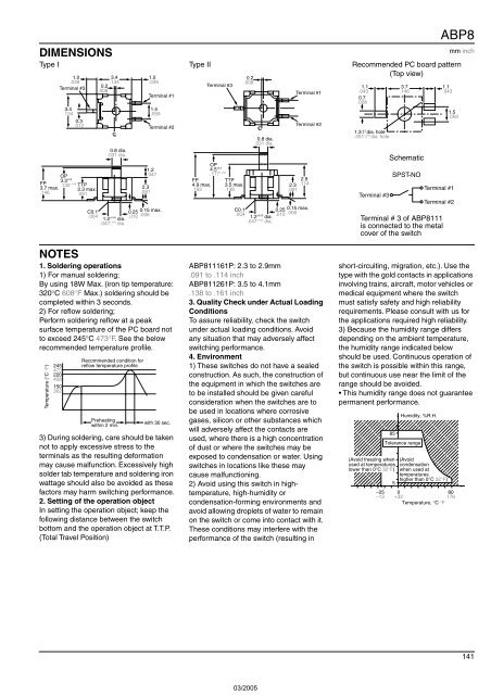
DIMENSIONS<br />
ABP8<br />
Type I Type II Recommended PC board pattern<br />
(Top view)<br />
FP<br />
3.7 max.<br />
.146<br />
1.0<br />
.039<br />
Terminal #3<br />
3.4<br />
.134<br />
OP<br />
3.3 ±0.2<br />
0.3<br />
.012<br />
.130 ±.008 TTP<br />
2.3 max.<br />
.091<br />
C0.1<br />
.004<br />
0.2<br />
.008<br />
3.4<br />
.134<br />
CL<br />
0.8 dia.<br />
.031 dia.<br />
1.2 ±0.05 dia.<br />
.047 ±.002 dia.<br />
1.2<br />
.047<br />
2.3<br />
.091<br />
1.0<br />
.039<br />
Terminal #1<br />
1.5<br />
.059<br />
Terminal #2<br />
0.25 0.15 max.<br />
.010 .006<br />
FP<br />
4.9 max.<br />
.193<br />
Terminal #3<br />
OP<br />
4.5 ±0.2<br />
.177 ±.008 TTP<br />
3.5 max.<br />
.138<br />
C0.1<br />
.004<br />
0.2<br />
.008<br />
CL<br />
0.8 dia.<br />
.031 dia.<br />
1.2 ±0.05 dia.<br />
.047 ±.002 dia.<br />
Terminal #1<br />
Terminal #2<br />
2.9<br />
2.3 .114<br />
.091<br />
0.25 0.15 max.<br />
.010 .006<br />
1.1<br />
.043<br />
0.7<br />
.028<br />
+0.2<br />
1.3 −0 dia. hole<br />
+.008<br />
.051 dia. hole<br />
−0<br />
Terminal #3<br />
3.7<br />
.146<br />
Schematic<br />
SPST-NO<br />
1.1<br />
.043<br />
mm inch<br />
1.5<br />
.059<br />
Terminal #1<br />
Terminal #2<br />
Terminal # 3 of ABP8111<br />
is connected to the metal<br />
cover of the switch<br />
NOTES<br />
1. Soldering operations<br />
1) For manual soldering;<br />
By using 18W Max. (iron tip temperature:<br />
320°C 608°F Max.) soldering should be<br />
completed within 3 seconds.<br />
2) For reflow soldering;<br />
Perform soldering reflow at a peak<br />
surface temperature of the PC board not<br />
to exceed 245°C 473°F. See the below<br />
recommended temperature profile.<br />
Temperature (°C °F)<br />
245<br />
473<br />
220<br />
428<br />
150<br />
302<br />
Recommended condition for<br />
reflow temperature profile<br />
Preheating<br />
within 2 min.<br />
with 30 sec.<br />
3) During soldering, care should be taken<br />
not to apply excessive stress to the<br />
terminals as the resulting deformation<br />
may cause malfunction. Excessively high<br />
solder tab temperature and soldering iron<br />
wattage should also be avoided as these<br />
factors may harm switching performance.<br />
2. Setting of the operation object<br />
In setting the operation object; keep the<br />
following distance between the switch<br />
bottom and the operation object at T.T.P.<br />
(Total Travel Position)<br />
ABP811161P: 2.3 to 2.9mm<br />
.091 to .114 inch<br />
ABP811261P: 3.5 to 4.1mm<br />
.138 to .161 inch<br />
3. Quality Check under Actual Loading<br />
Conditions<br />
To assure reliability, check the switch<br />
under actual loading conditions. Avoid<br />
any situation that may adversely affect<br />
switching performance.<br />
4. Environment<br />
1) These switches do not have a sealed<br />
construction. As such, the construction of<br />
the equipment in which the switches are<br />
to be installed should be given careful<br />
consideration when the switches are to<br />
be used in locations where corrosive<br />
gases, silicon or other substances which<br />
will adversely affect the contacts are<br />
used, where there is a high concentration<br />
of dust or where the switches may be<br />
exposed to condensation or water. Using<br />
switches in locations like these may<br />
cause malfunctioning.<br />
2) Avoid using this switch in hightemperature,<br />
high-humidity or<br />
condensation-forming environments and<br />
avoid allowing droplets of water to remain<br />
on the switch or come into contact with it.<br />
These conditions may interfere with the<br />
performance of the switch (resulting in<br />
short-circuiting, migration, etc.). Use the<br />
type with the gold contacts in applications<br />
involving trains, aircraft, motor vehicles or<br />
medical equipment where the switch<br />
must satisfy safety and high reliability<br />
requirements. Please consult with us for<br />
the applications required high reliability.<br />
3) Because the humidity range differs<br />
depending on the ambient temperature,<br />
the humidity range indicated below<br />
should be used. Continuous operation of<br />
the switch is possible within this range,<br />
but continuous use near the limit of the<br />
range should be avoided.<br />
• This humidity range does not guarantee<br />
permanent performance.<br />
;;;<br />
;<br />
;;;;;<br />
;;;;;;;<br />
;;;;;;;;;<br />
;;;;;;;;;;<br />
;;;;;;;;;;<br />
;;;;;;;;;<br />
;;;;;;;;<br />
;;;;;;<br />
;;;;<br />
;;<br />
–25<br />
–13<br />
85<br />
Humidity, %R.H.<br />
Tolerance range<br />
(Avoid freezing when (Avoid<br />
used at temperatures condensation<br />
lower than 0°C 32°F) when used at<br />
temperatures<br />
higher than 0°C 32°F)<br />
5<br />
0<br />
80<br />
+32<br />
176<br />
Temperature, °C °F<br />
141