Snap-Action Switches Detection Switches General Catalogue 2005
Snap-Action Switches Detection Switches General Catalogue 2005
Snap-Action Switches Detection Switches General Catalogue 2005

You also want an ePaper? Increase the reach of your titles
YUMPU automatically turns print PDFs into web optimized ePapers that Google loves.
NOTES<br />
1. Switch mounting<br />
Mount the switch with the hole cutting<br />
dimensions shown in the drawing.<br />
2. Adjustment of the operating device:<br />
With respect to the position of the<br />
operating device and the switch body, set<br />
the position as indicated in the condition<br />
on the right. If this condition is exceeded,<br />
the mechanical and electrical<br />
performance will be impaired. In addition,<br />
the force applied by the oprating device<br />
should be in a perpendicular direction.<br />
Even if the pushbutton is used in the full<br />
total travel position, there will be no<br />
influence on the life of the switch.<br />
Free condition<br />
Operating<br />
device<br />
O.T. 2mm type: 8mm .315inch min.<br />
O.T. 4mm type: 10mm .394inch min.<br />
Operating condition<br />
1 Form A, 2 Form A:<br />
2.4 to 3mm<br />
.094 to .118inch<br />
3 Form A: 2.4 to 4mm<br />
.094 to .157inch<br />
3. Confirming insulating distance<br />
Before mounting and wiring, the<br />
insulating distance between terminals<br />
and between the terminals and ground<br />
should be checked for assurance of<br />
proper distance. With respect to the<br />
terminal connections, it is recommended<br />
that receptacles with insulating sleeves or<br />
"Positive Lock Connector*" be used. Also<br />
consideration should be given to the<br />
wiring not to apply force to the terminal<br />
section normally.<br />
*Registered by AMP, Ltd.<br />
4. Regarding fastening lead wires to<br />
terminals<br />
Use .250 receptacle (terminal thickness<br />
0.8mm .031inch) or .110 receptacle<br />
(terminal thickness 0.5mm .020inch)<br />
should be used for connection. Make<br />
sure the sockets are straight. If they are<br />
skewed, the terminals will require<br />
excessive insertion force. The insertion<br />
force varies according to manufacturer’s<br />
AGX<br />
specifications. Check it for the sockets<br />
you are using.<br />
5. Material of the panel<br />
Steel sheet is recommended as the panel<br />
material. When using soft material,<br />
confirm the condition for actual use.<br />
6. Quality check under actual loading<br />
conditions<br />
To improve reliability, check the switch<br />
under actual loading conditions. Avoid<br />
any situation that may adversely affect<br />
switching performance.<br />
7. Avoid using and keeping switches<br />
in the following conditions.<br />
• In corrosive gases<br />
• In a dusty environment<br />
• Where silicon atomosphere prevails<br />
REFERENCE<br />
1. Outline of UL1054 test<br />
Overload test<br />
Standard type: 12.5A 250V AC<br />
(Power factor 0.75 to 0.8)<br />
High capacity type: 20A 250V AC<br />
(Power factor 0.75 to 0.8)<br />
Endurance test<br />
Standard type: 10A 250V AC<br />
(Power factor 0.75 to 0.8)<br />
High capacity type: 16A 250V AC<br />
(Power factor 0.75 to 0.8)<br />
After testing, temperature rise of<br />
terminals should be less than 30°C 86°F<br />
and no abnormality should be observed<br />
in characteristics.<br />
2. Outline of EN61058-1 test<br />
After switching 25,000 times on the<br />
+5<br />
above load condition at both 85 0 °C<br />
+41<br />
185 +32°F and 25±10°C 77±50°F,<br />
temperature rise of terminals should be<br />
less than 55°C 131°F and no abnormality<br />
should be observed in characteristics.<br />
24A<br />
50 to 100ms<br />
2 sec.<br />
4 sec.<br />
J7: 10A<br />
AC: 250V<br />
(Power<br />
factor 0.6)<br />
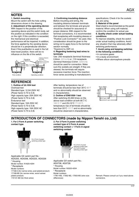
INTRODUCTION OF CONNECTORS (made by Nippon Tanshi co.,Ltd)<br />
1. For 2 Form A power switching<br />
contact type<br />
2. For 2 Form A power switching<br />
contact type of 2 Form A power<br />
switching contact + 1 Form A signal<br />
switching contact<br />
For 2 Form A power<br />
switching contact type<br />
For 2 Form A power<br />
switching contact type<br />
of 2 Form A power<br />
switching contact type<br />
Applicable GX switch part No.:<br />
AGX205, AGX206, AGX225, AGX226<br />
* Housing<br />
Model number: N1620-4204<br />
* Receptacle<br />
Model numbers<br />
17168-2 (for narrow wires, post-plated product)<br />
17168-M2 (for narrow wires, wood veneer<br />
plated product)<br />
172131-M2 (for thick wires)<br />
Applicable GX switch part No.:<br />
AGX706, AGX726<br />
* Housing<br />
Model number: N3220-4204<br />
* Receptacle<br />
Model numbers<br />
17901-M2, 17902-M2, 17903-M3 (wire size<br />
differences)<br />
Remark: Please consult us if you need above<br />
connectors.<br />
117