
You also want an ePaper? Increase the reach of your titles
YUMPU automatically turns print PDFs into web optimized ePapers that Google loves.
Introduction<br />
<strong>Chilled</strong> beams have been employed in European HVAC<br />
sensible cooling only applications for over twenty years.<br />
Within the past few years they have become a popular<br />
alternative to VAV systems in North America. The<br />
growing interest in chilled beams has been fueled by<br />
their energy saving potential, ease of use as well as<br />
their minimal space requirements.<br />
<strong>Chilled</strong> beams were originally developed to supersede<br />
the outputs achieved by passive radiant cooling ceiling<br />
systems. Sensible cooling capacities of “chilled” ceilings<br />
are limited by the chilled water supply temperature<br />
(must be maintained above dew point to prevent<br />
condensation from forming on their surfaces) and the<br />
total surface area available that can be „chilled‟.<br />
Obviously, this area is limited as other services<br />
(lighting, fire protection, air distribution & extract etc.)<br />
limit the degree of employment of the active ceiling<br />
surface such that their maximum space sensible cooling<br />
capacity is very typically less than 25 BTUH per square<br />
foot of floor area. As this is not sufficient for maintaining<br />
comfort especially in perimeter areas, chilled beams<br />
very quickly became the preferred solution in so much<br />
as they occupied less space, had fewer connection and<br />
most importantly offered sensible cooling outputs 2 to 3<br />
times that of „chilled‟ ceilings.<br />
INTRODUCTION TO CHILLED BEAMS<br />
<strong>Chilled</strong> beams feature finned chilled water heat exchanger<br />
cooling coils, capable of providing up to 1100<br />
BTUH of sensible cooling per foot of length and are<br />
designed to take advantage of the significantly higher<br />
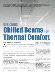
cooling efficiencies of water. Figure 1 illustrates that a<br />
one inch diameter water pipe can transport the same<br />
cooling energy as an 18 inch square air duct. The use<br />
of chilled beams can thus dramatically reduce air<br />
handler and ductwork sizes enabling more efficient use<br />
of both horizontal and vertical building space.<br />
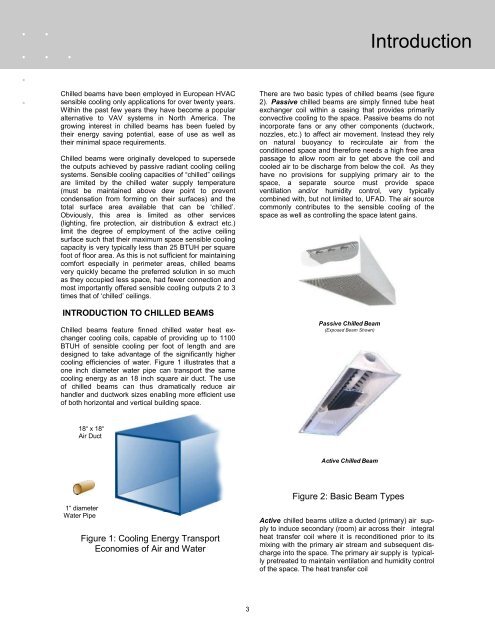
There are two basic types of chilled beams (see figure<br />
2). Passive chilled beams are simply finned tube heat<br />
exchanger coil within a casing that provides primarily<br />
convective cooling to the space. Passive beams do not<br />
incorporate fans or any other components (ductwork,<br />
nozzles, etc.) to affect air movement. Instead they rely<br />
on natural buoyancy to recirculate air from the<br />
conditioned space and therefore needs a high free area<br />
passage to allow room air to get above the coil and<br />
cooled air to be discharge from below the coil. As they<br />
have no provisions for supplying primary air to the<br />
space, a separate source must provide space<br />
ventilation and/or humidity control, very typically<br />
combined with, but not limited to, UFAD. The air source<br />
commonly contributes to the sensible cooling of the<br />
space as well as controlling the space latent gains.<br />
Passive <strong>Chilled</strong> <strong>Beam</strong><br />
(Exposed <strong>Beam</strong> Shown)<br />
18“ x 18“<br />
Air Duct<br />
Active <strong>Chilled</strong> <strong>Beam</strong><br />
1“ diameter<br />
Water Pipe<br />
Figure 1: Cooling Energy Transport<br />
Economies of Air and Water<br />
Figure 2: Basic <strong>Beam</strong> Types<br />
Active chilled beams utilize a ducted (primary) air supply<br />
to induce secondary (room) air across their integral<br />
heat transfer coil where it is reconditioned prior to its<br />
mixing with the primary air stream and subsequent discharge<br />
into the space. The primary air supply is typically<br />
pretreated to maintain ventilation and humidity control<br />
of the space. The heat transfer coil<br />
3