
You also want an ePaper? Increase the reach of your titles
YUMPU automatically turns print PDFs into web optimized ePapers that Google loves.
Active <strong>Beam</strong> Selection Examples<br />
The primary air supply is to be delivered at 55˚F with a<br />
dew point temperature of 52˚F (W = 0.0082 LBM H 2 O<br />
per pound dry air). The beams are to be located directly<br />
above the work benches in order to capture the most<br />
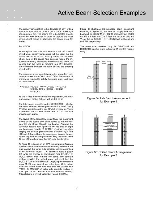
sensible heat. Figure 34 illustrates the bench layout for<br />
the lab.<br />
SOLUTION:<br />
As the space dew point temperature is 55.2˚F, a 56˚F<br />
chilled water supply temperature will be used. As the<br />
beams are to be located directly above the benches<br />
where most of the space heat sources reside, the induced<br />
air entering the beams will be assumed to be 2°F<br />
warmer than the room air resulting in a 21˚F temperature<br />
differential between the room air and the entering<br />
chilled water.<br />
The minimum primary air delivery to the space for ventilation<br />
purposes is 8 ACH-1, or 800 CFM. The amount of<br />
primary air required to satisfy the space latent load may<br />
be calculated as:<br />
Figure 35 illustrates the proposed beam placement.<br />
Referring to figure 19, the total air supply from each<br />
beam will be 666 CFM or 40 CFM per linear foot of slot.<br />
As A/2 is 8 feet and X is 7 feet, the value of VH 1 and<br />
VL 6 at the six foot (H - H1 = 4 feet) level will be 56 and<br />
86 FPM, respectively.<br />
The water side pressure drop for DID602-US and<br />
DID602-HC can be found in figures 37 and 39, respectively.<br />
Lab<br />
Benches<br />
8 feet<br />
(typical)<br />
CFM LATENT = q LATENT / 4840 x (W ROOM – W PRIMARY )<br />
= 2,000 / 4840 x (0.0092 – 0.0082)<br />
= 413 CFM<br />
As this is less than the ventilation requirement, the minimum<br />
primary airflow delivery will be 800 CFM.<br />
The total space sensible load is 42,000 BTUH. Ideally,<br />
the beam selected should provide 52.5 (42,000 / 800)<br />
BTUH of sensible cooling per CFM of primary air. Table<br />
4 indicates that DID602 beams with “C” nozzles can<br />
provide such a ratio.<br />
The layout of the laboratory would favor the placement<br />
of one or two beams over each bench, so we will consider<br />
the use of four (8) eight foot beams. Applying the<br />
correction factors from figure 46 we see that an eight<br />
foot beam can provide 25 CFM/LF of primary air while<br />
keeping the air side pressure drop of inches H 2 O. The<br />
NC level (39) would also be acceptable. In order to supply<br />
the required air changes (800 CFM), we would need<br />
32 feet of these beams or four (4) eight foot lengths.<br />
As figure 46 is based on an 18°F temperature difference<br />
between the air and chilled water entering the beam, we<br />
must correct the water side sensible cooling according<br />
to the correction factor (1.16) shown in table 6 (page<br />
38) while the primary air contribution (567 BTUH/LF or<br />
17,400 BTUH total) remains the same. The sensible<br />
cooling provided the chilled water coil must thus be<br />
24,600 BTUH or 769 BTUH/LF. Applying the correction<br />
factor (1.16) from table 6, we enter figure 46 to determine<br />
the chilled water flow rate that will provide 663<br />
(769/1.16) BTUH/LF of water side sensible cooling or<br />
1,230 (663 + 567) BTUH/LF of total sensible cooling.<br />
This relates to a chilled water flow rate of 1.0 GPM.<br />
Figure 34: Lab Bench Arrangement<br />
for Example 5<br />
16 feet<br />
(typical)<br />
DID602-US Active<br />
<strong>Chilled</strong> <strong>Beam</strong><br />
(8 ft. Long, "C" Nozzles)<br />
(typical of 4)<br />
Figure 35: <strong>Chilled</strong> <strong>Beam</strong> Arrangement<br />
for Example 5<br />
37