
Create successful ePaper yourself
Turn your PDF publications into a flip-book with our unique Google optimized e-Paper software.
Passive <strong>Beam</strong> Selection<br />
The required sensible heat removal of the beams is the<br />
total sensible heat gain of the space (8,640 BTUH) less<br />
that removed by the air supply (2,040 BTUH) or 6,600<br />
BTUH.<br />
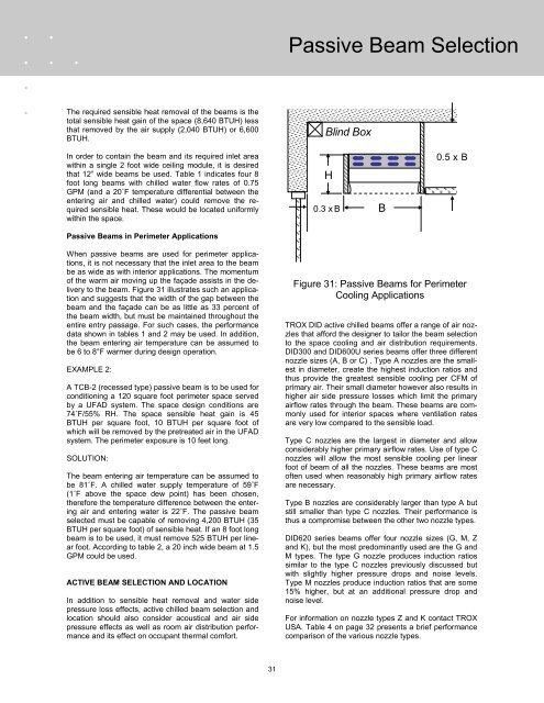
Blind Box<br />
In order to contain the beam and its required inlet area<br />
within a single 2 foot wide ceiling module, it is desired<br />
that 12” wide beams be used. Table 1 indicates four 8<br />
foot long beams with chilled water flow rates of 0.75<br />
GPM (and a 20˚F temperature differential between the<br />
entering air and chilled water) could remove the required<br />
sensible heat. These would be located uniformly<br />
within the space.<br />
H<br />
0.3 x B<br />
B<br />
0.5 x B<br />
Passive <strong>Beam</strong>s in Perimeter Applications<br />
When passive beams are used for perimeter applications,<br />
it is not necessary that the inlet area to the beam<br />
be as wide as with interior applications. The momentum<br />
of the warm air moving up the façade assists in the delivery<br />
to the beam. Figure 31 illustrates such an application<br />
and suggests that the width of the gap between the<br />
beam and the façade can be as little as 33 percent of<br />
the beam width, but must be maintained throughout the<br />
entire entry passage. For such cases, the performance<br />
data shown in tables 1 and 2 may be used. In addition,<br />
the beam entering air temperature can be assumed to<br />
be 6 to 8°F warmer during design operation.<br />
EXAMPLE 2:<br />
A TCB-2 (recessed type) passive beam is to be used for<br />
conditioning a 120 square foot perimeter space served<br />
by a UFAD system. The space design conditions are<br />
74˚F/55% RH. The space sensible heat gain is 45<br />
BTUH per square foot, 10 BTUH per square foot of<br />
which will be removed by the pretreated air in the UFAD<br />
system. The perimeter exposure is 10 feet long.<br />
SOLUTION:<br />
The beam entering air temperature can be assumed to<br />
be 81˚F. A chilled water supply temperature of 59˚F<br />
(1˚F above the space dew point) has been chosen,<br />
therefore the temperature difference between the entering<br />
air and entering water is 22˚F. The passive beam<br />
selected must be capable of removing 4,200 BTUH (35<br />
BTUH per square foot) of sensible heat. If an 8 foot long<br />
beam is to be used, it must remove 525 BTUH per linear<br />
foot. According to table 2, a 20 inch wide beam at 1.5<br />
GPM could be used.<br />
ACTIVE BEAM SELECTION AND LOCATION<br />
In addition to sensible heat removal and water side<br />
pressure loss effects, active chilled beam selection and<br />
location should also consider acoustical and air side<br />
pressure effects as well as room air distribution performance<br />
and its effect on occupant thermal comfort.<br />
Figure 31: Passive <strong>Beam</strong>s for Perimeter<br />
Cooling Applications<br />
<strong>TROX</strong> DID active chilled beams offer a range of air nozzles<br />
that afford the designer to tailor the beam selection<br />
to the space cooling and air distribution requirements.<br />
DID300 and DID600U series beams offer three different<br />
nozzle sizes (A, B or C) . Type A nozzles are the smallest<br />
in diameter, create the highest induction ratios and<br />
thus provide the greatest sensible cooling per CFM of<br />
primary air. Their small diameter however also results in<br />
higher air side pressure losses which limit the primary<br />
airflow rates through the beam. These beams are commonly<br />
used for interior spaces where ventilation rates<br />
are very low compared to the sensible load.<br />
Type C nozzles are the largest in diameter and allow<br />
considerably higher primary airflow rates. Use of type C<br />
nozzles will allow the most sensible cooling per linear<br />
foot of beam of all the nozzles. These beams are most<br />
often used when reasonably high primary airflow rates<br />
are necessary.<br />
Type B nozzles are considerably larger than type A but<br />
still smaller than type C nozzles. Their performance is<br />
thus a compromise between the other two nozzle types.<br />
DID620 series beams offer four nozzle sizes (G, M, Z<br />
and K), but the most predominantly used are the G and<br />
M types. The type G nozzle produces induction ratios<br />
similar to the type C nozzles previously discussed but<br />
with slightly higher pressure drops and noise levels.<br />
Type M nozzles produce induction ratios that are some<br />
15% higher, but at an additional pressure drop and<br />
noise level.<br />
For information on nozzle types Z and K contact <strong>TROX</strong><br />
USA. Table 4 on page 32 presents a brief performance<br />
comparison of the various nozzle types.<br />
31