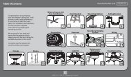
Installation and Operation Manual For Hunter Ceiling ... - Hunter Fan
Installation and Operation Manual For Hunter Ceiling ... - Hunter Fan
Installation and Operation Manual For Hunter Ceiling ... - Hunter Fan

Create successful ePaper yourself
Turn your PDF publications into a flip-book with our unique Google optimized e-Paper software.
®<br />
STEP 6 - INSTALLING THE REMOTE<br />
Remote Model #: UC7067RC<br />
Ratings: 120 VAC, 60 Hz, 1.0 Amp <strong>Fan</strong><br />
250 Watts inc<strong>and</strong>escent light<br />
WARNINGS<br />
• To avoid possible electrical<br />
shock, before installing the<br />
remote, be sure that all<br />
power is disconnected by<br />
turning off the circuit<br />
breakers to the outlet box.<br />
• All wiring must be performed<br />
in accordance with<br />
national <strong>and</strong> local electrical<br />
codes. If you are unfamiliar<br />
with the wiring codes,<br />
you should use a qualified<br />
electrician.<br />
• To avoid overheating <strong>and</strong><br />
possible damage to other<br />
equipment, do not install<br />
to control a receptacle,<br />
fluorescent light fixture,<br />
motor operated appliance,<br />
or transformer-supplied<br />
appliance. Use only to control<br />
one paddle-blade ceiling<br />
fan <strong>and</strong> inc<strong>and</strong>escent<br />
light fixture.<br />
Note: This device complies<br />
with Part 15 of the FCC<br />
Rules. <strong>Operation</strong> is subject<br />
to the following two conditions:<br />
(1) this device may not<br />
cause harmful interference,<br />
<strong>and</strong> (2) this device must accept<br />
any interference received,<br />
including interference<br />
that may cause undesired<br />
operation.<br />
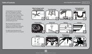
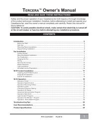
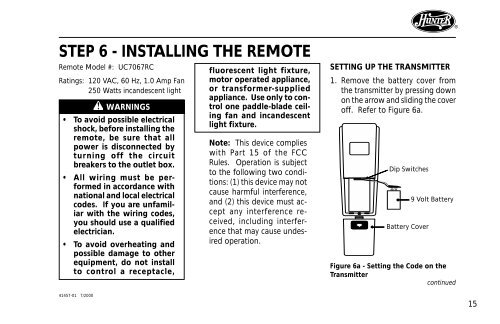
SETTING UP THE TRANSMITTER<br />
1. Remove the battery cover from<br />
the transmitter by pressing down<br />
on the arrow <strong>and</strong> sliding the cover<br />
off. Refer to Figure 6a.<br />
Dip Switches<br />
Battery Cover<br />
9 Volt Battery<br />
Figure 6a - Setting the Code on the<br />
Transmitter<br />
continued<br />
41457-01 7/2000<br />
15