Installation and Operation Manual For Hunter Ceiling ... - Hunter Fan
Installation and Operation Manual For Hunter Ceiling ... - Hunter Fan
Installation and Operation Manual For Hunter Ceiling ... - Hunter Fan

You also want an ePaper? Increase the reach of your titles
YUMPU automatically turns print PDFs into web optimized ePapers that Google loves.
®<br />
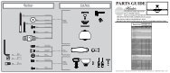
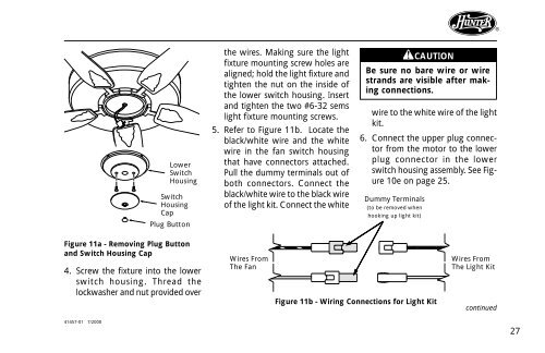
Lower<br />
Switch<br />
Housing<br />
Switch<br />
Housing<br />
Cap<br />
Plug Button<br />
the wires. Making sure the light<br />
fixture mounting screw holes are<br />
aligned; hold the light fixture <strong>and</strong><br />
tighten the nut on the inside of<br />
the lower switch housing. Insert<br />
<strong>and</strong> tighten the two #6-32 sems<br />
light fixture mounting screws.<br />
5. Refer to Figure 11b. Locate the<br />
black/white wire <strong>and</strong> the white<br />
wire in the fan switch housing<br />
that have connectors attached.<br />
Pull the dummy terminals out of<br />
both connectors. Connect the<br />
black/white wire to the black wire<br />
of the light kit. Connect the white<br />
CAUTION<br />
Be sure no bare wire or wire<br />
str<strong>and</strong>s are visible after making<br />
connections.<br />
wire to the white wire of the light<br />
kit.<br />
6. Connect the upper plug connector<br />
from the motor to the lower<br />
plug connector in the lower<br />
switch housing assembly. See Figure<br />
10e on page 25.<br />
Dummy Terminals<br />
(to be removed when<br />
hooking up light kit)<br />
Figure 11a - Removing Plug Button<br />
<strong>and</strong> Switch Housing Cap<br />
4. Screw the fixture into the lower<br />
switch housing. Thread the<br />
lockwasher <strong>and</strong> nut provided over<br />
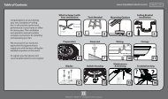
Wires From<br />
The <strong>Fan</strong><br />
Figure 11b - Wiring Connections for Light Kit<br />
Wires From<br />
The Light Kit<br />
continued<br />
41457-01 7/2000<br />
27