Installation and Operation Manual For Hunter Ceiling ... - Hunter Fan
Installation and Operation Manual For Hunter Ceiling ... - Hunter Fan
Installation and Operation Manual For Hunter Ceiling ... - Hunter Fan

Create successful ePaper yourself
Turn your PDF publications into a flip-book with our unique Google optimized e-Paper software.
®<br />
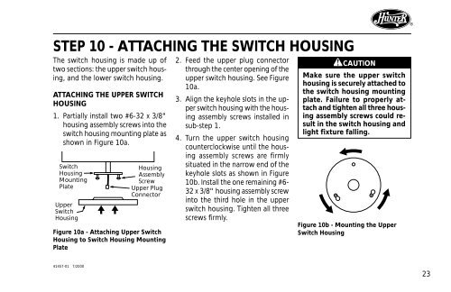
STEP 10 - ATTACHING THE SWITCH HOUSING<br />
The switch housing is made up of<br />
two sections: the upper switch housing,<br />
<strong>and</strong> the lower switch housing.<br />
ATTACHING THE UPPER SWITCH<br />
HOUSING<br />
1. Partially install two #6-32 x 3/8"<br />
housing assembly screws into the<br />
switch housing mounting plate as<br />
shown in Figure 10a.<br />
Switch<br />
Housing<br />
Mounting<br />
Plate<br />
Upper<br />
Switch<br />
Housing<br />
Housing<br />
Assembly<br />
Screw<br />
Upper Plug<br />
Connector<br />
Figure 10a - Attaching Upper Switch<br />
Housing to Switch Housing Mounting<br />
Plate<br />
2. Feed the upper plug connector<br />
through the center opening of the<br />
upper switch housing. See Figure<br />
10a.<br />
3. Align the keyhole slots in the upper<br />
switch housing with the housing<br />
assembly screws installed in<br />
sub-step 1.<br />
4. Turn the upper switch housing<br />
counterclockwise until the housing<br />
assembly screws are firmly<br />
situated in the narrow end of the<br />
keyhole slots as shown in Figure<br />
10b. Install the one remaining #6-<br />
32 x 3/8" housing assembly screw<br />
into the third hole in the upper<br />
switch housing. Tighten all three<br />
screws firmly.<br />
CAUTION<br />
Make sure the upper switch<br />
housing is securely attached to<br />
the switch housing mounting<br />
plate. Failure to properly attach<br />
<strong>and</strong> tighten all three housing<br />
assembly screws could result<br />
in the switch housing <strong>and</strong><br />
light fixture falling.<br />
Figure 10b - Mounting the Upper<br />
Switch Housing<br />
41457-01 7/2000<br />
23