Diploma - Max Planck Institute for Solid State Research
Diploma - Max Planck Institute for Solid State Research
Diploma - Max Planck Institute for Solid State Research

You also want an ePaper? Increase the reach of your titles
YUMPU automatically turns print PDFs into web optimized ePapers that Google loves.
26 4 EuRh 2 Si 2 – semi-localized electrons<br />
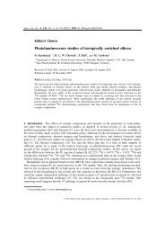
Figure 4.3: (a) comparative band structure plot of high-symmetry cuts of SPG 123 (red)<br />
and SPG 139 (green) in the BZ; the corresponding paths have been sketched in (b)+(c);<br />
in (c) additionally the backfolding is sketched: the band structure of the upper green plane is<br />
reflected along the red plane (BZ border of SPG 123) onto the one of the lower green plane<br />
(see the arrow); the band structure along Γ-Z-Γ indicates the reflecting character of the red<br />
plane; since SPG 123 has a cuboid BZ, the bisection can be infinitely repeated resulting in the<br />
mentioned projected band structure<br />
translational invariant quantity – the unit cell – is superior and backfolding does not<br />
occur since the corresponding components of the potential’s Fourier trans<strong>for</strong>mation<br />
vanish. But in PE projected band structure occurs, because the initial state is the sum<br />
of all states in the region of the surface (can have different k z ) and the indeterminacy of<br />
k z in the final state due to finite penetrating depth. There<strong>for</strong>e, the surface configuration<br />
should consist of projected bulk band structure due to the change in periodicity as<br />
well as of surface states / resonances depending on the respective boundary conditions.<br />
Both parts are important to compare the surface / bulk sensitivity of the measurements.<br />
Speer et. al. [39] made a detailed analysis exemplarily <strong>for</strong> silver on the topic of emerging<br />
band structure in photoemission. Since semi-bulk and surface have the same space<br />
group, the projection onto the k x × k y plane <strong>for</strong> the surface BZ will be denoted by a<br />
bar over the respecting high-symmetry points.<br />
Below, the relationship between the BZs of SPG 123 / 139 depicted in fig. 4.2 will be<br />
discussed. A cut at k z = 0 is illustrated denoting the boundary of the BZs inplane as<br />
solid and structures of lower and higher parallel layers by dotted lines. Hence the stacking<br />
of the bulk BZ in the x/y-direction is shifted by (0, 0, ±1/2) <strong>for</strong> the next-neighbour<br />
BZ, the Z-point is the mid-distance point of the Γ-Γ path <strong>for</strong> each spatial direction (x,<br />
y, z, -x, -y, -z). Neglecting body-centered symmetry halves the BZ (cf. the 3D image in<br />
fig. 4.2) and each Z-point is mapped onto Γ. These backfolding from SPG 139 to 123<br />
will be exemplarily shown <strong>for</strong> two high-symmetry directions: the diagonal path Z-X-Γ<br />
(blue) gets mirrored with respect to X reassembling the Γ-M-Γ path in SPG 123 whereat<br />
the folding orientation is given by the arrows. Correspondingly, Z-X maps onto Γ-X.