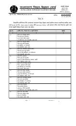
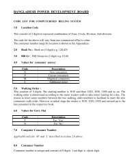
- Page 1 and 2: BANGLADESH POWER DEVELOPMENT BOARD
- Page 3 and 4: Section 1 Description of the Projec
- Page 5 and 6: Section 2 Scope of Work Re-Powering
- Page 7 and 8: 2.7 Other Electrical System 2.8 Eme
- Page 9 and 10: 2. Scope of Work 2.0 Scope of Work.
- Page 11 and 12: s. Cooling and ventilating system.
- Page 13 and 14: Evaporator and Super-heater of the
- Page 15 and 16: There are 3 (Three) feed water pump
- Page 17 and 18: No of heater Heating surface Steam
- Page 19 and 20: Description of Sealing Oil Pump(AC)
- Page 21 and 22: 0.4 kV bus, EDG will start and supp
- Page 23 and 24: • Rated low voltage : 6.6 kV •
- Page 25 and 26: l. One (1) lot 230 KV Control & Rel
- Page 27 and 28: in his supply, and shall provide ne
- Page 29 and 30: 2.30 Effluent Treatment Plant Efflu
- Page 31 and 32: 3. Power Plant Arrangement 3.1 Gene
- Page 33: 3.2 Guarantee The steam turbine gen
- Page 37 and 38: 3.3.6 Closed circuit cooling water
- Page 39 and 40: The generators shall be connected t
- Page 41 and 42: given of the outside of the enclosu
- Page 43 and 44: 4.0 Gas Turbine and Ancillary Equip
- Page 45 and 46: 4.3.2.1 Vibration Critical Speed Th
- Page 47 and 48: 2. Compressor wash water quality To
- Page 49 and 50: 4.3.2.9 Air Inlet System The air fi
- Page 51 and 52: Section-5 Heat Recovery Steam Gener
- Page 53 and 54: 5. Heat Recovery Steam Generator an
- Page 55 and 56: 5.1.9 Steam Purging Following acid
- Page 57 and 58: (2) Chemical Feed Pipe The chemical
- Page 59 and 60: 5.2.4 Economiser The economiser sha
- Page 61 and 62: An approval system of safety valve
- Page 63 and 64: (e) All special supporting hangers,
- Page 65 and 66: 5.2.10 Valves All valves shall be o
- Page 67 and 68: Sensors for temperature, pressure,
- Page 69 and 70: prevent sticking and leakage. Suita
- Page 71 and 72: 6. Existing Steam Turbine And Ancil
- Page 73 and 74: Description of Shaft Turning Gear M
- Page 75 and 76: RPM 1000 Current 222 Amps Stand by
- Page 77 and 78: 6.11 Valves 6.12 Generator There ar
- Page 79 and 80: Power 22 KW Voltage 230/400 V(∆Y)
- Page 81 and 82: RPM 1000 Current 53 A Description o
- Page 83 and 84: Section 7 Gas Turbine Generator and
- Page 85 and 86:
7. Generator and Ancillary Equipmen
- Page 87 and 88:
aced, blocked and supported against
- Page 89 and 90:
discharge or suppress excitation fo
- Page 91 and 92:
(4) Safety shutters actuated by ins
- Page 93 and 94:
- Current transformer : Three (3),
- Page 95 and 96:
- Circuit breaker : One (1) for eac
- Page 97 and 98:
8. TRANSFORMERS 8.1 General 8.1.1 R
- Page 99 and 100:
a. 230 KV CIRCUIT - lightning impul
- Page 101 and 102:
(3) Oil Preservation System: Oil im
- Page 103 and 104:
The full insulation shall be applie
- Page 105 and 106:
±8x1.25%. 8.4.2 Output Each auxili
- Page 107 and 108:
9. 230 Kv Outdoor Switchgear, Equip
- Page 109 and 110:
(3) Ratings a. Rated voltage : 245
- Page 111 and 112:
fittings between each phase and con
- Page 113 and 114:
sealed Electromagnetic type voltage
- Page 115 and 116:
k. Each current transformer shall b
- Page 117 and 118:
9.3.2 DESIGN CRITERIA The steel str
- Page 119 and 120:
e. Step-bolts : one (1) lot f. “R
- Page 121 and 122:
Section 10 6.6 Kv Switchgear and Lo
- Page 123 and 124:
10. 6.6 kV SWITCHGEAR AND LOW TENSI
- Page 125 and 126:
Rated normal current Incoming and b
- Page 127 and 128:
Section 11 Control and Protection R
- Page 129 and 130:
11. Control and Protection Equipmen
- Page 131 and 132:
- Automatic synchronising equipment
- Page 133 and 134:
ee. AVR failure x ff. Emergency Tri
- Page 135 and 136:
One (1) lot One (1) lot One (1) lot
- Page 137 and 138:
(1) Pressure Measurement Pressure s
- Page 139 and 140:
11.11 DELETED. range of 85 % to 115
- Page 141 and 142:
shall be followed in the design of
- Page 143 and 144:
(namely that, of the approved DCS)
- Page 145 and 146:
The following functions must be rea
- Page 147 and 148:
11.11.7.5 Group Controls The auto-s
- Page 149 and 150:
The HP and LP steam pressure contro
- Page 151 and 152:
11.11.7.7 Operator Command and Supe
- Page 153 and 154:
(a) Commonality of equipment, facil
- Page 155 and 156:
Analog value storage of the Process
- Page 157 and 158:
Standard weather stations with all
- Page 159 and 160:
12. CABLING AND GROUNDING 12.1 Gene
- Page 161 and 162:
12.2.2. 6.6 kV XLPE POWER CABLES Th
- Page 163 and 164:
core type. The size of the conducto
- Page 165 and 166:
Section 13 DC Power Supply System R
- Page 167 and 168:
13.0 DC and UPS Systems The DC and
- Page 169 and 170:
13.2 UPS Performance Static uninter
- Page 171 and 172:
14. Lighting And Small Power Supply
- Page 173 and 174:
c. The size shall be adequate to li
- Page 175 and 176:
The wall switches shall be of the e
- Page 177 and 178:
15. FUEL GAS HANDLING FACILITIES 15
- Page 179 and 180:
Section 16 Fire Detection & Protect
- Page 181 and 182:
16. Fire Detection & Protection Fac
- Page 183 and 184:
mm diameter. The underground pipewo
- Page 185 and 186:
17. Communication Facilities 17.1 G
- Page 187 and 188:
h. Operator intrusion into an estab
- Page 189 and 190:
Ammeter for measuring the emitter c
- Page 191 and 192:
• video matrix switcher and contr
- Page 193 and 194:
18. Maintenance Facilities 18.1 Ove
- Page 195 and 196:
18.1.3 TYPE OF CRANE 18.1.4 RATING
- Page 197 and 198:
anchors and other electrical equipm
- Page 199 and 200:
18.1.10 SITE TESTS (1) Control and
- Page 201 and 202:
Section 19 Tests and Inspections Re
- Page 203 and 204:
19. Tests and Inspections 19.1 GENE
- Page 205 and 206:
19.2.4 GENERATOR 19.2.5 EXCITER All
- Page 207 and 208:
"Voltage transformers” - General
- Page 209 and 210:
(3) Reliability Test Period a. The
- Page 211 and 212:
(4) Performance and Acceptance Test
- Page 213 and 214:
Insulation resistance test using 50
- Page 215 and 216:
ound copies of all site test sheet
- Page 217 and 218:
Section 20 Civil Works Re-Powering
- Page 219 and 220:
20.6.11 Transportation 20.6.12 Curi
- Page 221 and 222:
20.1.3 SITE INVESTIGATION The Contr
- Page 223 and 224:
20.3 EARTHWORKS 20.3.1 GENERAL The
- Page 225 and 226:
until the work has been inspected a
- Page 227 and 228:
the piles. Due consideration shall
- Page 229 and 230:
casing in concrete or such other me
- Page 231 and 232:
a+b+e or a+b+c+f or a+b+d+f 20.4.4
- Page 233 and 234:
approved standard. When required by
- Page 235 and 236:
20.6.11 TRANSPORTATION 20.6.12 CURI
- Page 237 and 238:
In a flight of stairs Rise 3 mm In
- Page 239 and 240:
20.7.1.2 Aggregate Sub-base Materia
- Page 241 and 242:
warping or cracking. When placing t
- Page 243 and 244:
(14) days. Ponding of the surface o
- Page 245 and 246:
Man-holes, inspection chambers and
- Page 247 and 248:
Colour of paint shall be as directe
- Page 249 and 250:
This pump shall be operated in conj
- Page 251 and 252:
20.11 Ducts The concrete ducts to i
- Page 253 and 254:
Section 21 Building Works Re-Poweri
- Page 255 and 256:
21. Building Works 21.1 General The
- Page 257 and 258:
adopted standards or codes shall be
- Page 259 and 260:
Outside temperature : 36 0 C Inside
- Page 261 and 262:
(6) Welding Procedure (7) Paint Det
- Page 263 and 264:
chips, gravel or crushed stone, or
- Page 265 and 266:
pallets, and other hidden timber sh
- Page 267 and 268:
21.5.9 Floor Laying (1) PVC Floorin
- Page 269 and 270:
protection of the tiling from all d
- Page 271 and 272:
Section 22 Spare Parts Re-Powering
- Page 273 and 274:
22. Spare Parts 22.1 Spares & consu
- Page 275 and 276:
BACKGROUND INFORMATION: Bangladesh
- Page 277 and 278:
- Overhauling of all electrical mot
- Page 279 and 280:
GENERAL CONDITIONS OF LTSA CONTRACT
- Page 281 and 282:
8. LIMITATION OF LIABILITY 8.1 The
- Page 283 and 284:
- Failing to pay the LTSA provider
- Page 285 and 286:
the Head of the power plant. 16. CO
- Page 287 and 288:
Section 23 Appendices Re-Powering G
- Page 289 and 290:
Annexure -1 ANALYSIS OF NATURAL GAS
- Page 291 and 292:
Indicative Single Line Diagram of E
- Page 293 and 294:
Re-Powering Ghorasal 210 MW 3 rd Un
- Page 295 and 296:
Re-Powering Ghorasal 210 MW 3 rd Un
- Page 297 and 298:
Re-Powering Ghorasal 210 MW 3 rd Un
- Page 299 and 300:
Standards for Industrial Effluent o
- Page 301 and 302:
Re-Powering Ghorasal 210 MW 3 rd Un
- Page 303 and 304:
Re-Powering Ghorasal 210 MW 3 rd Un
- Page 305:
Re-Powering Ghorasal 210 MW 3 rd Un