
You also want an ePaper? Increase the reach of your titles
YUMPU automatically turns print PDFs into web optimized ePapers that Google loves.
a nail. The screw makes for a solid<br />
connection, and the nail prevents<br />
the balusters fror-n rotating.<br />
Rail Cap -Although it's irutalled<br />
after the trim blocks, there's no reason<br />
the rail cap can't be made in advance.<br />
It's 71/2" shorter than the rail below<br />
it because the cap fits against a 3/-1"<br />
trim piece on each end.Wide bevels<br />
cut in the top face of the rail cap<br />
provide a comfortable hand rest<br />
(Photo, right). And grooves routed in<br />
the bottom create a drip edge.<br />
lime for llim<br />
Once the railings are constructed,<br />
it's time to install them on the porch.<br />
This is where the trin.r pieces I rnentioned<br />
earlier come into play.<br />
The trim pieces do two things.<br />
First, they add depth ro the lower<br />
part of the column.And second, they<br />
capture the ends of the railings, providing<br />
a solid connection with the<br />
colunrns (Railing Assentbly, page 44).<br />
All the trim pieces are nrade from<br />
3/a"-thick cedar.Two of these pieces<br />
form an L-shaped corner assembly<br />
that covers each corner ofthe column<br />
(lllustratiorr, belotu left). It's assembled<br />
exactly the salne way as the post<br />
cladding - with locking rabbet joinrs<br />
(scc pa.qe 47).Thc rernaining pieces<br />
are just blocks of wood attached to<br />
the colunrns onc piece Jt il tinlc.<br />
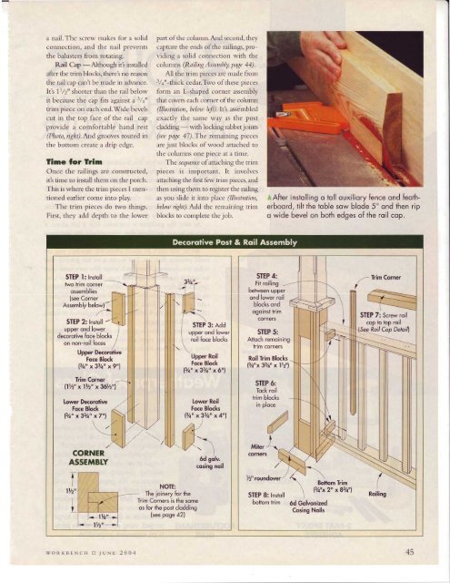
The scqucncc of attaching the trin-r<br />
pieces is inrportant. It involves<br />
attaching the first Gw trinr pieces, and<br />
then using thenr to register the railing<br />
as you slide it into place (lllustration,<br />
Itclow ri.qht). Add thc renrairring trirrr<br />
blocks to cor.nplete the job.<br />
After instolling o toll ouxiliory fence ond feotherboord,<br />
tilt the toble sow blode 5" ond then rip<br />
o wide bevel on both edges of the roil cop.<br />
STEP l: Instoll<br />
two trim corner<br />
ossemblies<br />
(see Corner<br />
Assembly below)-<br />
STEP 2: Instoll -<br />
upper ond lower<br />
decorotive foce blocks<br />
on non-roil foces<br />
Upper Decorotive<br />
Foce Block<br />
1t1on y33/4,, x9"l<br />
Trim Corner<br />
11Y2" x lr/2" x361/z"l<br />
lower Decorolive<br />
Foce Block<br />
l3h" x33a" x7"l<br />
Upper Roil<br />
Foce Block<br />
131a,, a33/an x6r'l<br />
lower Roil<br />
Foce Blocks<br />
1314,'x33h,, x4rrl<br />
aTrimCorner<br />
STEP 7: Screw roil<br />
cop to top roil<br />
(See Ro/ Cop Detoif<br />
./<br />
CORNER<br />
ASSEMBTY<br />
I<br />
ll42"<br />
I<br />
lys'!<br />
lt/zu<br />
NOTE:<br />
The ioinery for the<br />
Trim Corners is the some<br />
os for the post clodding<br />
(see poge 42)<br />
woRKITENCH fl JUNE 2004 45


![Til]tl](https://img.yumpu.com/45878240/1/190x245/tiltl.jpg?quality=85)