Parameter List Edition 04/03 SINAMICS G110 - Automatyka Siemens
Parameter List Edition 04/03 SINAMICS G110 - Automatyka Siemens
Parameter List Edition 04/03 SINAMICS G110 - Automatyka Siemens

You also want an ePaper? Increase the reach of your titles
YUMPU automatically turns print PDFs into web optimized ePapers that Google loves.
<strong>Parameter</strong>s <strong>04</strong>/<strong>03</strong><br />
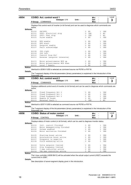
r0054 CO/BO: Act. control word 1 Min: -<br />
Datatype: U16 Unit: - Def: -<br />
P-Group: COMMANDS Max: -<br />
Level<br />
3<br />
Displays first control word of inverter (in bit format) and can be used to diagnose which commands are<br />
active.<br />
Bitfields:<br />
Bit00 ON/OFF1 0 NO 1 YES<br />
Bit01 OFF2: Electrical stop 0 YES 1 NO<br />
Bit02 OFF3: Fast stop 0 YES 1 NO<br />
Bit<strong>03</strong> Pulse enable 0 NO 1 YES<br />
Bit<strong>04</strong> RFG enable 0 NO 1 YES<br />
Bit05 RFG start 0 NO 1 YES<br />
Bit06 Setpoint enable 0 NO 1 YES<br />
Bit07 Fault acknowledge 0 NO 1 YES<br />
Bit08 JOG right 0 NO 1 YES<br />
Bit09 JOG left 0 NO 1 YES<br />
Bit10 Control from PLC 0 NO 1 YES<br />
Bit11 Reverse (setpoint inversion) 0 NO 1 YES<br />
Bit13 Motor potentiometer MOP up 0 NO 1 YES<br />
Bit14 Motor potentiometer MOP down 0 NO 1 YES<br />
Bit15 Local / Remote 0 NO 1 YES<br />
Notice:<br />
Identical to r2<strong>03</strong>6 if USS is selected as command source via P0700 or P0719.<br />
Details:<br />
The 7-segment display of the bit-parameters (binary parameters) is explained in the Introduction of the<br />
<strong>Parameter</strong> <strong>List</strong>.<br />
r0055 CO/BO: Act. control word 2 Min: -<br />
Datatype: U16 Unit: - Def: -<br />
P-Group: COMMANDS Max: -<br />
Displays additional control word of inverter (in bit format) and can be used to diagnose which commands are<br />
active.<br />
Bitfields:<br />
Bit00 Fixed frequency Bit 0 0 NO 1 YES<br />
Bit01 Fixed frequency Bit 1 0 NO 1 YES<br />
Bit02 Fixed frequency Bit 2 0 NO 1 YES<br />
Bit09 Enable DC brake 0 NO 1 YES<br />
Bit13 External fault 1 0 YES 1 NO<br />
Notice:<br />
Identical to r2<strong>03</strong>7 if USS is selected as command source via P0700 or P0719.<br />
Details:<br />
The 7-segment display of the bit-parameters (binary parameters) is explained in the Introduction of the<br />
<strong>Parameter</strong> <strong>List</strong>.<br />
r0056 CO/BO: Status of motor control Min: -<br />
Datatype: U16 Unit: - Def: -<br />
P-Group: CONTROL Max: -<br />
Displays status of motor control (in bit format), which can be used to diagnose inverter status.<br />
Bitfields:<br />
Bit00 Init. control finished 0 NO 1 YES<br />
Bit01 Motor demagnetizing finished 0 NO 1 YES<br />
Bit02 Pulses enabled 0 NO 1 YES<br />
Bit<strong>04</strong> Motor excitation finished 0 NO 1 YES<br />
Bit05 Starting boost active 0 NO 1 YES<br />
Bit06 Acceleration boost active 0 NO 1 YES<br />
Bit07 Frequency is negative 0 NO 1 YES<br />
Bit08 Field weakening active 0 NO 1 YES<br />
Bit09 Volts setpoint limited 0 NO 1 YES<br />
Bit10 Slip frequency limited 0 NO 1 YES<br />
Bit13 I-max controller active 0 NO 1 YES<br />
Bit14 Vdc-max controller active 0 NO 1 YES<br />
Notice:<br />
The I-max controller (r0056 Bit13) will be activated when the actual output current (r0027) exceeds the<br />
current limit in r0067.<br />
Details:<br />
See description of seven-segment display given in the introduction.<br />
Level<br />
3<br />
Level<br />
2<br />
<strong>Parameter</strong> <strong>List</strong> <strong>SINAMICS</strong> <strong>G110</strong><br />
18 6SL3298-0BA11-0BP0