Parameter List Edition 04/03 SINAMICS G110 - Automatyka Siemens
Parameter List Edition 04/03 SINAMICS G110 - Automatyka Siemens
Parameter List Edition 04/03 SINAMICS G110 - Automatyka Siemens

Create successful ePaper yourself
Turn your PDF publications into a flip-book with our unique Google optimized e-Paper software.
<strong>04</strong>/<strong>03</strong> <strong>Parameter</strong>s<br />
r1801 CO: Act. pulse frequency Min: -<br />
Datatype: U16 Unit: kHz Def: -<br />
P-Group: INVERTER Max: -<br />
Level<br />
3<br />
Actual pulse frequency of power switches in inverter.<br />
Notice:<br />
Under certain conditions, the inverter changes the switching frequency from the value selected in P1800. At<br />
start-up, the pulse frequency is set to the minimum value; below an operating frequency of 2 Hz, the pulse<br />
frequency is halved.<br />
P2000 Reference frequency Min: 1.00<br />
CStat: CT Datatype: Float Unit: Hz Def: 50.00<br />
P-Group: COMM Active: first confirm QuickComm.: No Max: 650.00<br />
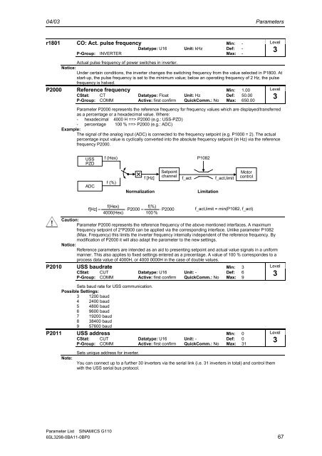
<strong>Parameter</strong> P2000 represents the reference frequency for frequency values which are displayed/transferred<br />
as a percentage or a hexadecimal value. Where:<br />
- hexadecimal 4000 H ==> P2000 (e.g.: USS-PZD)<br />
- percentage 100 % ==> P2000 (e.g.: ADC)<br />
Example:<br />
The signal of the analog input (ADC) is connected to the frequency setpoint (e.g. P1000 = 2). The actual<br />
percentage input value is cyclically converted into the absolute frequency setpoint (in Hz) via the reference<br />
frequency P2000.<br />
Level<br />
3<br />
USS<br />
PZD<br />
f (Hex)<br />
P1082<br />
ADC<br />
f (%)<br />
f [Hz]<br />
Normalization<br />
Setpoint<br />
channel<br />
f_act<br />
Limitation<br />
f_act,limit<br />
Motor<br />
control<br />
f(Hex)<br />
f(%)<br />
f[Hz] = ⋅P2000<br />
= ⋅P2000<br />
f_act,limit = min(P1082, f_act)<br />
4000(Hex)<br />
100 %<br />
Caution:<br />
<strong>Parameter</strong> P2000 represents the reference frequency of the above mentioned interfaces. A maximum<br />
frequency setpoint of 2*P2000 can be applied via the corresponding interface. Unlike parameter P1082<br />
(Max. Frequency) this limits the inverter frequency internally independent of the reference frequency. By<br />
modification of P2000 it will also adapt the parameter to the new settings.<br />
Notice:<br />
Reference parameters are intended as an aid to presenting setpoint and actual value signals in a uniform<br />
manner. This also applies to fixed settings entered as a precentage. A value of 100 % correspondes to a<br />
process data value of 4000H, or 4000 0000H in the case of double values.<br />
P2010 USS baudrate Min: 3<br />
Level<br />
CStat: CUT Datatype: U16 Unit: - Def: 6<br />
3<br />
P-Group: COMM Active: first confirm QuickComm.: No Max: 9<br />
Sets baud rate for USS communication.<br />
Possible Settings:<br />
3 1200 baud<br />
4 2400 baud<br />
5 4800 baud<br />
6 9600 baud<br />
7 19200 baud<br />
8 38400 baud<br />
9 57600 baud<br />
P2011 USS address Min: 0<br />
CStat: CUT Datatype: U16 Unit: - Def: 0<br />
P-Group: COMM Active: first confirm QuickComm.: No Max: 31<br />
Level<br />
3<br />
Note:<br />
Sets unique address for inverter.<br />
You can connect up to a further 30 inverters via the serial link (i.e. 31 inverters in total) and control them<br />
with the USS serial bus protocol.<br />
<strong>Parameter</strong> <strong>List</strong> <strong>SINAMICS</strong> <strong>G110</strong><br />
6SL3298-0BA11-0BP0 67