Parameter List Edition 04/03 SINAMICS G110 - Automatyka Siemens
Parameter List Edition 04/03 SINAMICS G110 - Automatyka Siemens
Parameter List Edition 04/03 SINAMICS G110 - Automatyka Siemens

Create successful ePaper yourself
Turn your PDF publications into a flip-book with our unique Google optimized e-Paper software.
<strong>Parameter</strong>s <strong>04</strong>/<strong>03</strong><br />
P1335 Slip compensation Min: 0.0<br />
CStat: CUT Datatype: Float Unit: % Def: 0.0<br />
P-Group: CONTROL Active: Immediately QuickComm.: No Max: 600.0<br />
Level<br />
3<br />
Dynamically adjusts output frequency of inverter so that motor speed is kept constant independent of motor<br />
load.<br />
In the V/f-control, the motor speed will always be less than the command speed due to the slip speed. For a<br />
given speed command, the speed will drop as load is increased. The speed regulation of drive can be<br />
improved by the technique known as slip compensation.<br />
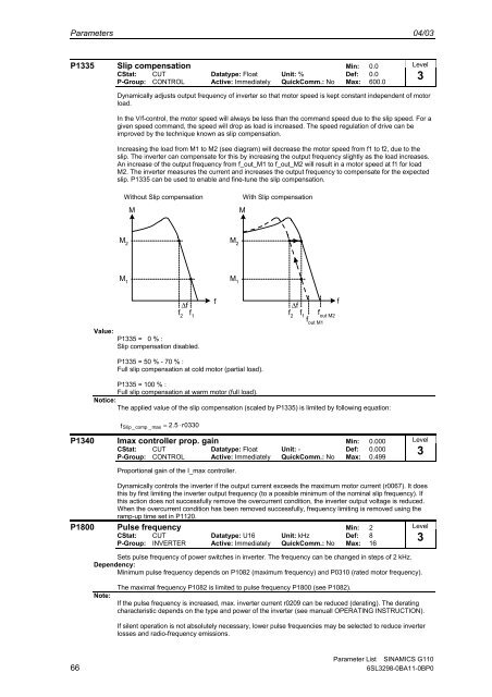
Increasing the load from M1 to M2 (see diagram) will decrease the motor speed from f1 to f2, due to the<br />
slip. The inverter can compensate for this by increasing the output frequency slightly as the load increases.<br />
An increase of the output frequency from f_out_M1 to f_out_M2 will result in a motor speed at f1 for load<br />
M2. The inverter measures the current and increases the output frequency to compensate for the expected<br />
slip. P1335 can be used to enable and fine-tune the slip compensation.<br />
Without Slip compensation<br />
M<br />
M<br />
With Slip compensation<br />
M 2<br />
M 2<br />
M 1<br />
M 1<br />
Value:<br />
∆f<br />
f 2<br />
f 1<br />
P1335 = 0 % :<br />
Slip compensation disabled.<br />
f<br />
∆f<br />
f 2<br />
f 1<br />
f out M2<br />
f out M1<br />
f<br />
P1335 = 50 % - 70 % :<br />
Full slip compensation at cold motor (partial load).<br />
P1335 = 100 % :<br />
Full slip compensation at warm motor (full load).<br />
Notice:<br />
The applied value of the slip compensation (scaled by P1335) is limited by following equation:<br />
f Slip<br />
_ comp _ max<br />
= 2.5 ⋅ r<strong>03</strong>30<br />
P1340 Imax controller prop. gain Min: 0.000<br />
CStat: CUT Datatype: Float Unit: - Def: 0.000<br />
P-Group: CONTROL Active: Immediately QuickComm.: No Max: 0.499<br />
Level<br />
3<br />
Proportional gain of the I_max controller.<br />
Dynamically controls the inverter if the output current exceeds the maximum motor current (r0067). It does<br />
this by first limiting the inverter output frequency (to a possible minimum of the nominal slip frequency). If<br />
this action does not successfully remove the overcurrent condition, the inverter output voltage is reduced.<br />
When the overcurrent condition has been removed successfully, frequency limiting is removed using the<br />
ramp-up time set in P1120.<br />
P1800 Pulse frequency Min: 2<br />
Level<br />
CStat: CUT Datatype: U16 Unit: kHz Def: 8<br />
3<br />
P-Group: INVERTER Active: Immediately QuickComm.: No Max: 16<br />
Sets pulse frequency of power switches in inverter. The frequency can be changed in steps of 2 kHz.<br />
Dependency:<br />
Minimum pulse frequency depends on P1082 (maximum frequency) and P<strong>03</strong>10 (rated motor frequency).<br />
Note:<br />
The maximal frequency P1082 is limited to pulse frequency P1800 (see P1082).<br />
If the pulse frequency is increased, max. inverter current r0209 can be reduced (derating). The derating<br />
characteristic depends on the type and power of the inverter (see manuall OPERATING INSTRUCTION).<br />
If silent operation is not absolutely necessary, lower pulse frequencies may be selected to reduce inverter<br />
losses and radio-frequency emissions.<br />
<strong>Parameter</strong> <strong>List</strong> <strong>SINAMICS</strong> <strong>G110</strong><br />
66 6SL3298-0BA11-0BP0