5000 Series Indicators Instruction Manual - MaRCo
5000 Series Indicators Instruction Manual - MaRCo
5000 Series Indicators Instruction Manual - MaRCo

You also want an ePaper? Increase the reach of your titles
YUMPU automatically turns print PDFs into web optimized ePapers that Google loves.
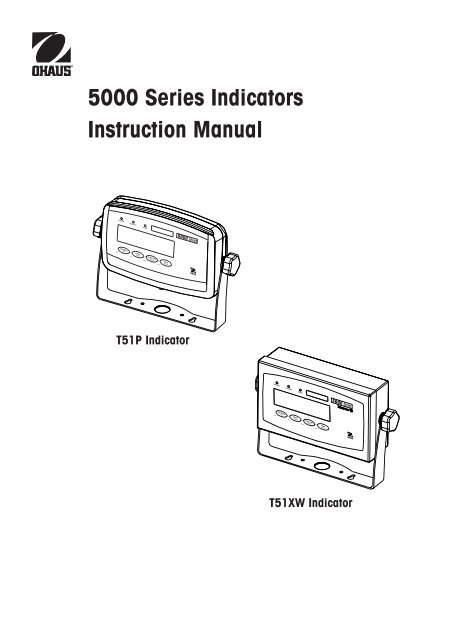
<strong>5000</strong> <strong>Series</strong> <strong>Indicators</strong><br />
<strong>Instruction</strong> <strong>Manual</strong><br />
T51P Indicator<br />
T51XW Indicator
Modification Sheet to this manual p/n 80251400<br />
Section Explanation<br />
2.2.1 For connecting bases with a connector to a T51XW (which does not have the external connector), a Load Cell Cable Adapter<br />
Kit p/n 80500736 is available as an accessory. This kit connects to the terminal block inside the T51XW and has an external<br />
connector on the other end.<br />
3.4.1 Reset the Setup menu to the factory defaults (except Range, Capacity and Graduation)<br />
3.4.4 Note: Range 2 graduation is retained even under half capacity until the scale returns to zero<br />
3.4.5 Note: Units oz, lb:oz and C (custom) will not be valid as Power On units when Range is set to Dual. The next available unit<br />
will be displayed instead.<br />
3.4.9 When Legal for Trade is on, the following Menu settings are effected:<br />
Range, Graduation, Power On unit, Auto-Tare, Retain Zero, Gross Indication, and Print Output settings are locked; Zero<br />
Range is locked at 2%; Stable Range is locked at 1d; AZT is set to 0.5d; Capacity is read-only; Continuous Print is disabled;<br />
Lock Unit and Lock Mode are turned on; Calibration functions except for Cal Test are hidden; IP and CP RS232 commands<br />
are disabled.<br />
3.4.10 Beeper volume settings are Off, Low (default), High<br />
3.5.2 Stable Range settings are: 0.5d, 1d, 2d, 3d, 5d<br />
3.9.1 Note: If LFT is on, the following Print menu settings are not reset: Stable<br />
3.10 Handshake default setting is “none”<br />
5.2 Output Format:<br />
Field: Weight Space* Unit Space* Stability Space* G/N Space* Term. Char(s)<br />
Length: 9 1 5 1 1 1 N 1 *<br />
*Each field is followed by a single delimiting space (ASCII: 32)<br />
Definitions:<br />
Weight – up to 9 characters, right justified, “-“ at immediate left of most significant character (if negative).<br />
Unit – up to 5 characters<br />
Stability – “?” character is printed if not stable. If weight is stable, neither “?” nor following space is printed.<br />
G/N – “NET” printed if weight is net weight, “G”, “B”, or nothing (depending on GROSS menu setting – Sec. 3.5.7) printed if weight is a gross weight.<br />
*Terminating Character(s) – terminating character(s) printed depending on FEED menu setting (CR,LF / 4xCR,LF / ASCII:12, refer also to Sec. 3.9.5).<br />
6.3 D51Pxxx scales utilize a load cell cable that is plugged onto the indicator. For EC and OIML type approved applications, the<br />
plugged connection must be sealed using the Load Cell Sealing Collar p/n 80500737.<br />
8.2 Table 8-3:<br />
Interface Cable/PC 9-pin, T51P 80500525<br />
Interface Cable/PC 25-pin, T51P 80500524<br />
Interface Cable/Printer SF-42, T51P 80500571<br />
Interface Cable/PC 9-pin, T51XW 80500552<br />
Interface Cable/PC 25-pin, T51XW 80500553<br />
Interface Cable/Printer SF-42, T51XW 80500574<br />
Load Cell Cable Adapter Kit 80500736<br />
Load Cell Cable Sealing Collar 80500737<br />
Note: The next revision of this manual will be updated with these modifications.
<strong>5000</strong> <strong>Series</strong> <strong>Indicators</strong><br />
EN-<br />
TABLE OF CONTENTS<br />
1. INTRODUCTION..........................................................................................................................................EN-5<br />
1.1 Safety Precautions......................................................................................................................................EN-5<br />
1.1.1 Relay Option Safety Precautions.........................................................................................................EN-5<br />
1.2 Overview of Parts and Controls ...................................................................................................................EN-6<br />
1.3 Control Functions.....................................................................................................................................EN-10<br />
2. INSTALLATION..........................................................................................................................................EN-11<br />
2.1 Unpacking...............................................................................................................................................EN-11<br />
2.2 External Connections................................................................................................................................EN-11<br />
2.2.1 Scale Base with Connector to T51P .................................................................................................EN-11<br />
2.2.2 RS232 Interface Cable to T51P........................................................................................................EN-11<br />
2.2.3 AC Power to T51P .........................................................................................................................EN-11<br />
2.2.4 AC Power to T51XW.......................................................................................................................EN-11<br />
2.2.5 Battery Power to T51P....................................................................................................................EN-11<br />
2.2.6 Mounting Bracket...........................................................................................................................EN-12<br />
2.3 Internal Connections.................................................................................................................................EN-12<br />
2.3.1 Opening the Housing.......................................................................................................................EN-12<br />
2.3.2 Scale Base Without Connector to T51P or T51XW .............................................................................EN-12<br />
2.3.3 RS232 Interface Cable to T51XW......................................................................................................EN-13<br />
2.3.4 Footswitch to T51P or T51XW...........................................................................................................EN-13<br />
2.4 T51P Rear Housing Orientation..................................................................................................................EN-13<br />
2.5 Mounting Bracket.....................................................................................................................................EN-13<br />
3. SETTINGS................................................................................................................................................EN-14<br />
3.1 Menu Structure.........................................................................................................................................EN-14<br />
3.2 Menu Navigation......................................................................................................................................EN-16<br />
3.3 Calibration Menu......................................................................................................................................EN-16<br />
3.3.1 Zero Calibration.............................................................................................................................EN-17<br />
3.3.2 Span Calibration...........................................................................................................................EN-17<br />
3.3.3 Linearity Calibration.......................................................................................................................EN-18<br />
3.3.4 Calibration Test.............................................................................................................................EN-19<br />
3.3.5 Geographical Adjustment Factor......................................................................................................EN-19<br />
3.3.6 End Calibration.............................................................................................................................EN-19<br />
3.4 Setup Menu.............................................................................................................................................EN-21<br />
3.4.1 Reset...........................................................................................................................................EN-21<br />
3.4.2 Range..........................................................................................................................................EN-21<br />
3.4.3 Capacity.......................................................................................................................................EN-21<br />
3.4.4 Graduation...................................................................................................................................EN-22<br />
3.4.5 Power On Unit...............................................................................................................................EN-22<br />
3.4.6 Zero Range...................................................................................................................................EN-22<br />
3.4.7 Auto-Tare.....................................................................................................................................EN-23<br />
3.4.8 Retain Weight Data........................................................................................................................EN-23<br />
3.4.9 Legal for Trade..............................................................................................................................EN-23<br />
3.4.10 Beeper Volume..............................................................................................................................EN-24
EN-<br />
<strong>5000</strong> <strong>Series</strong> <strong>Indicators</strong><br />
TABLE OF CONTENTS (Cont.)<br />
3.4.11 Beeper Signal................................................................................................................................EN-24<br />
3.4.12 Button Beeper...............................................................................................................................EN-24<br />
3.4.13 End Setup.....................................................................................................................................EN-24<br />
3.5 Readout Menu..........................................................................................................................................EN-24<br />
3.5.1 Reset...........................................................................................................................................EN-25<br />
3.5.2 Stabile Range...............................................................................................................................EN-25<br />
3.5.3 Filter............................................................................................................................................EN-25<br />
3.5.4 Auto-Zero Tracking........................................................................................................................EN-25<br />
3.5.5 Backlight......................................................................................................................................EN-26<br />
3.5.6 Auto Off Timer...............................................................................................................................EN-26<br />
3.5.7 Gross Indicator..............................................................................................................................EN-26<br />
3.5.8 End Readout..................................................................................................................................EN-26<br />
3.6 Mode Menu.............................................................................................................................................EN-26<br />
3.6.1 Reset...........................................................................................................................................EN-27<br />
3.6.2 Weighing Mode.............................................................................................................................EN-27<br />
3.6.3 Parts Counting Mode.....................................................................................................................EN-27<br />
3.6.4 Parts Counting Optimize.................................................................................................................EN-27<br />
3.6.5 Percent Weighing Mode.................................................................................................................EN-27<br />
3.6.6 Dynamic Weighing Mode...............................................................................................................EN-27<br />
3.6.7 Check Weighing Mode...................................................................................................................EN-28<br />
3.6.8 End Mode.....................................................................................................................................EN-28<br />
3.7 Unit Menu................................................................................................................................................EN-28<br />
3.7.1 Reset...........................................................................................................................................EN-28<br />
3.7.2 Kilogram Unit................................................................................................................................EN-28<br />
3.7.3 Gram Unit.....................................................................................................................................EN-28<br />
3.7.4 Pound Unit...................................................................................................................................EN-29<br />
3.7.5 Ounce Unit...................................................................................................................................EN-29<br />
3.7.6 Pound Ounce Unit.........................................................................................................................EN-29<br />
3.7.7 Tonnes Unit..................................................................................................................................EN-29<br />
3.7.8 Custom Unit..................................................................................................................................EN-29<br />
3.7.9 End Unit.......................................................................................................................................EN-30<br />
3.8 GMP Menu..............................................................................................................................................EN-30<br />
3.8.1 Reset...........................................................................................................................................EN-30<br />
3.8.2 Date Type.....................................................................................................................................EN-30<br />
3.8.3 Date Set.......................................................................................................................................EN-31<br />
3.8.4 Time Type....................................................................................................................................EN-31<br />
3.8.5 Time Set.......................................................................................................................................EN-31<br />
3.8.6 User ID.........................................................................................................................................EN-32<br />
3.8.7 Project ID.....................................................................................................................................EN-32<br />
3.8.8 Scale ID.......................................................................................................................................EN-32<br />
3.8.7 End GMP......................................................................................................................................EN-32<br />
3.9 Print 1, Print 2 Menus...............................................................................................................................EN-33<br />
3.9.1 Reset...........................................................................................................................................EN-33<br />
3.9.2 Print Stable data Only....................................................................................................................EN-33<br />
3.9.3 Auto Print.....................................................................................................................................EN-33<br />
3.9.4 Print Content Sub-menu.................................................................................................................EN-34
<strong>5000</strong> <strong>Series</strong> <strong>Indicators</strong><br />
EN-<br />
TABLE OF CONTENTS (Cont.)<br />
3.9.5 Layout Sub-menu..........................................................................................................................EN-36<br />
3.9.6 List Menu Settings.........................................................................................................................EN-36<br />
3.9.7 End Print......................................................................................................................................EN-36<br />
3.10 COM 1, COM 2 Menus.............................................................................................................................EN-36<br />
3.10.1 Reset...........................................................................................................................................EN-36<br />
3.10.2 Baud...........................................................................................................................................EN-37<br />
3.10.3 Parity...........................................................................................................................................EN-37<br />
3.10.4 Stop Bit........................................................................................................................................EN-37<br />
3.10.5 Handshake...................................................................................................................................EN-37<br />
3.10.6 Address........................................................................................................................................EN-37<br />
3.10.7 Alternate Command Sub-menu.......................................................................................................EN-38<br />
3.10.8 End COM 1 or End COM 2..............................................................................................................EN-38<br />
3.11 I/O Menu................................................................................................................................................EN-38<br />
3.11.1 Reset...........................................................................................................................................EN-38<br />
3.11.2 External Input................................................................................................................................EN-39<br />
3.11.3 Input Beep....................................................................................................................................EN-39<br />
3.11.4 Relay Output.................................................................................................................................EN-39<br />
3.11.5 End.............................................................................................................................................EN-40<br />
3.12 Menu Lock Menu ....................................................................................................................................EN-40<br />
3.12.1 Reset...........................................................................................................................................EN-40<br />
3.12.2 Lock Calibration............................................................................................................................EN-40<br />
3.12.3 Lock Setup....................................................................................................................................EN-41<br />
3.12.4 Lock Readout................................................................................................................................EN-41<br />
3.12.5 Lock Mode...................................................................................................................................EN-41<br />
3.12.6 Lock Unit......................................................................................................................................EN-41<br />
3.12.7 Lock Print 1..................................................................................................................................EN-41<br />
3.12.8 Lock Print 2..................................................................................................................................EN-41<br />
3.12.9 Lock Com 1..................................................................................................................................EN-41<br />
3.12.10 Lock Com 2................................................................................................................................EN-41<br />
3.12.11 Lock GMP...................................................................................................................................EN-42<br />
3.12.12 Lock I/O.....................................................................................................................................EN-42<br />
3.12.13 End Lock....................................................................................................................................EN-42<br />
3.13 Key Lock Menu........................................................................................................................................EN-42<br />
3.13.1 Reset...........................................................................................................................................EN-42<br />
3.13.2 Lock All Buttons............................................................................................................................EN-42<br />
3.13.3 Lock Off Button.............................................................................................................................EN-42<br />
3.13.4 Lock Zero Button...........................................................................................................................EN-42<br />
3.13.5 Lock Print Button...........................................................................................................................EN-43<br />
3.13.6 Lock Unit Button............................................................................................................................EN-43<br />
3.13.7 Lock Function Button.....................................................................................................................EN-43<br />
3.13.8 Lock Mode Button.........................................................................................................................EN-43<br />
3.13.9 Lock Tare Button...........................................................................................................................EN-43<br />
3.13.10 Lock Menu Button........................................................................................................................EN-43<br />
3.13.11 End Lock....................................................................................................................................EN-43<br />
3.14 Security Switch.................................................................................................................................EN-43
EN-<br />
<strong>5000</strong> <strong>Series</strong> <strong>Indicators</strong><br />
TABLE OF CONTENTS (Cont.)<br />
4. OPERATION.............................................................................................................................................EN-44<br />
4.1 Turning Indicator On/Off............................................................................................................................EN-44<br />
4.2 Zero Operation.........................................................................................................................................EN-44<br />
4.3 <strong>Manual</strong> Tare............................................................................................................................................EN-44<br />
4.4 Pre-Set Tare.............................................................................................................................................EN-44<br />
4.5 Auto-Tare.................................................................................................................................................EN-44<br />
4.6 Changing Units of Measure........................................................................................................................EN-45<br />
4.7 Printing Data............................................................................................................................................EN-45<br />
4.8 Application Modes....................................................................................................................................EN-45<br />
4.8.1 Weighing......................................................................................................................................EN-45<br />
4.8.2 Parts Counting..............................................................................................................................EN-45<br />
4.8.3 Percent Weighing..........................................................................................................................EN-46<br />
4.8.4 Check Weighing............................................................................................................................EN-47<br />
4.8.5 Dynamic Weighing........................................................................................................................EN-48<br />
5. SERIAL COMMUNICATION..........................................................................................................................EN-49<br />
5.1 Interface Commands.................................................................................................................................EN-49<br />
5.2 Output Format..........................................................................................................................................EN-50<br />
5.3 Printouts..................................................................................................................................................EN-50<br />
6. LEGAL FOR TRADE....................................................................................................................................EN-52<br />
6.1 Settings...................................................................................................................................................EN-52<br />
6.2 Verification...............................................................................................................................................EN-52<br />
6.3 Sealing....................................................................................................................................................EN-52<br />
7. MAINTENANCE.........................................................................................................................................EN-53<br />
7.1 Model T51P Cleaning...............................................................................................................................EN-53<br />
7.2 Model T51XW Cleaning.............................................................................................................................EN-53<br />
7.3 Troubleshootting.......................................................................................................................................EN-53<br />
7.4 Service Information...................................................................................................................................EN-54<br />
8. TECHNICAL DATA......................................................................................................................................EN-55<br />
8.1 Specifications...........................................................................................................................................EN-55<br />
8.2 Accessories and Options...........................................................................................................................EN-56<br />
8.3 Drawings and Dimensions........................................................................................................................EN-57<br />
8.4 Compliance.............................................................................................................................................EN-58
<strong>5000</strong> <strong>Series</strong> <strong>Indicators</strong><br />
EN-<br />
1. INTRODUCTION<br />
This manual contains installation, operation and maintenance instructions for the T51P and T51XW <strong>Indicators</strong>. Please read this<br />
manual completely before installation and operation.<br />
1.1 Safety Precautions<br />
For safe and dependable operation of this equipment, please comply with the following safety precautions:<br />
• Verify that the input voltage range printed on the data label matches the local AC power to be used.<br />
• Make sure that the power cord does not pose a potential obstacle or tripping hazard.<br />
• Use only approved accessories and peripherals.<br />
• Operate the equipment only under ambient conditions specified in these instructions.<br />
• Disconnect the equipment from the power supply when cleaning.<br />
• Do not operate the equipment in hazardous or unstable environments.<br />
• Do not immerse the equipment in water or other liquids.<br />
• Service should only be performed by authorized personnel.<br />
• The T51XW is supplied with a grounded power cable. Use only with a compatible grounded power outlet.<br />
1.1.1 Relay Option Safety Precautions<br />
This equipment may have an optional AC or DC Relay Option board installed. This option allows external devices to be<br />
controlled by the Indicator.<br />
CAUTION: ELECTRICAL SHOCK HAZARD. REMOVE ALL POWER CONNECTIONS TO THE INDICATOR<br />
BEFORE SERVICING OR MAKING INTERNAL CONNECTIONS. THE HOUSING SHOULD ONLY BE OPENED BY<br />
AUTHORIZED AND QUALIFIED PERSONNEL, SUCH AS AN ELECTRICAL TECHNICIAN.<br />
Before making connections to the Relay terminals, remove power from the system. If the system contains an optional<br />
rechargeable battery system, be sure that the ON/ZERO Off button is used to fully turn off the system after removing the AC power<br />
plug.<br />
More detailed installation instructions are included with the Relay Option Kit when purchased.
EN-<br />
<strong>5000</strong> <strong>Series</strong> <strong>Indicators</strong><br />
1. Overview of Parts and Controls<br />
1<br />
2<br />
3<br />
4<br />
5<br />
6<br />
7<br />
8<br />
9<br />
10<br />
TABLE 1-1. T51P PARTS.<br />
Item Description<br />
1 Data Label<br />
2 Front Housing<br />
3 Control Panel<br />
4 Adjusting Knob (2)<br />
5 Mounting Bracket<br />
6 Security Screw<br />
7 Data Label<br />
8 Rear Housing<br />
9 Battery Cover<br />
10 Screw (4)<br />
11 Power Receptacle<br />
12 Hole plug for option<br />
13 Strain relief for alternate<br />
load cell connection<br />
14 Load Cell Connector<br />
15 Hole plug for option<br />
16 RS232 Connector<br />
11 12 13 14 15 16<br />
Figure 1-1. T51P Indicator.
<strong>5000</strong> <strong>Series</strong> <strong>Indicators</strong><br />
EN-<br />
1. Overview of Parts and Controls (Cont.)<br />
1<br />
2<br />
3<br />
4<br />
5<br />
6<br />
7<br />
TABLE 1-2. T51XW PARTS.<br />
Item Description<br />
1 Data Label<br />
2 Front Housing<br />
3 Control Panel<br />
4 Adjusting Knob (2)<br />
5 Mounting Bracket<br />
6 Screw (4)<br />
7 Rear housing<br />
8 Data Label<br />
9 Strain relief for option<br />
10 Strain relief for RS232<br />
11 Strain relief for option<br />
12 Strain relief for option<br />
13 Strain relief for Load Cell<br />
Cable<br />
14 Power cord<br />
8<br />
9 10 11 12 13 14<br />
Figure 1-2. T51XW Indicator.
EN-<br />
<strong>5000</strong> <strong>Series</strong> <strong>Indicators</strong><br />
1. Overview of Parts and Controls (Cont.)<br />
1 2 3 4 7<br />
5 6<br />
Figure 1-3. Main PC Board.<br />
TABLE 1-3. MAIN PC BOARD.<br />
Item Description<br />
1 Sense Jumper W1<br />
2 Alternate Load Cell Terminal Block J4<br />
3 Sense Jumper W2<br />
4 Security Switch SW2<br />
5 External input Terminal Block J9<br />
6 RS232 Terminal Block J7 (T51XW only)<br />
7 Load Cell Connector
<strong>5000</strong> <strong>Series</strong> <strong>Indicators</strong><br />
EN-<br />
1. Overview of Parts and Controls (Cont.)<br />
1 2 3 4 5 6 7 8 9<br />
27<br />
26<br />
25<br />
24<br />
23<br />
22<br />
21<br />
20<br />
<br />
19<br />
18<br />
17<br />
16 15 14 13 12<br />
11<br />
10<br />
Figure 1-4. Controls and <strong>Indicators</strong>.<br />
TABLE 1-4. CONTROL PANEL.<br />
No. Designation<br />
1 UNDER LED<br />
2 ACCEPT LED<br />
3 OVER LED<br />
4 Capacity Label Window<br />
5 Brackets (not used)<br />
6 Kilogram, gram symbols<br />
7 Scale symbol (not used)<br />
8 Range symbol<br />
9 Percent symbol<br />
10 Pound, Ounce, Pound:<br />
ounce symbols<br />
11 Tonne symbol<br />
12 Battery charge symbol<br />
13 Custom unit symbol<br />
14 Dynamic symbol<br />
No. Designation<br />
15 TARE Menu-Cal button<br />
16 Pieces symbol<br />
17 FUNCTION Mode button<br />
18 PRINT Units button<br />
19 ON/ZERO Off button<br />
20 Pointer symbols (not<br />
used)<br />
21 Brutto, Gross symbols<br />
22 Preset Tare, Tare<br />
symbols<br />
23 Stable weight Indicator<br />
24 Negative symbol<br />
25 Center of Zero Indicator<br />
26 NET symbol<br />
27 7-segment Display
EN-10<br />
<strong>5000</strong> <strong>Series</strong> <strong>Indicators</strong><br />
1. Control Functions<br />
TABLE 1-5. CONTROL FUNCTIONS.<br />
Button<br />
Primary Function<br />
(Short Press)<br />
ON/ZERO<br />
Turns the Indicator<br />
PRINT<br />
Sends the current value<br />
FUNCTION<br />
Initiates an application<br />
TARE<br />
Performs a tare<br />
on.<br />
to the selected COM<br />
mode.<br />
operation.<br />
ports if AUTOPRINT is<br />
If Indicator is On, sets<br />
set to Off.<br />
Temporarily displays the<br />
zero.<br />
active mode’s reference<br />
data.<br />
Secondary Function<br />
(Long Press)<br />
Off<br />
Turns the Indicator off.<br />
Units<br />
Changes the weighing<br />
Mode<br />
Allows changing the<br />
Menu-Cal<br />
Enter the User menu.<br />
Unit.<br />
application mode.<br />
Press and hold allows<br />
scrolling through modes.<br />
Menu Function<br />
(Short Press)<br />
Yes<br />
Accepts the current<br />
No<br />
Advances to the next<br />
Back<br />
Moves Back to previous<br />
Exit<br />
Exits the User menu.<br />
setting on the display.<br />
menu or menu item.<br />
menu item.<br />
Aborts the calibration in<br />
Rejects the current<br />
Decrements the value.<br />
progress.<br />
setting on the display<br />
and advances to the<br />
next available setting.<br />
Increments the value.
<strong>5000</strong> <strong>Series</strong> <strong>Indicators</strong><br />
EN-11<br />
2. INSTALLATION<br />
2.1 Unpacking<br />
Unpack the following items:<br />
• T51P or T51XW Indicator<br />
• AC Power Cord (T51P only)<br />
• Mounting Bracket<br />
• Knobs (2)<br />
2.2 External Connections<br />
• Capacity Label Sheet<br />
• LFT Sealing kit<br />
• <strong>Instruction</strong> <strong>Manual</strong> CD<br />
• Warranty Card<br />
2.2.1 Scale Base with Connector to T51P<br />
Ohaus bases with a connector can be attached to the external load cell connector (Figure 1-1, item 14). Refer to section 2.3.2<br />
for bases without a connector.<br />
2.2.2 RS232 interface Cable to T51P<br />
Connect the optional RS232 cable to the RS232 connector (Figure 1-1, item 16).<br />
Pin Connection<br />
1 N/C<br />
2 TXD<br />
3 RXD<br />
4 N/C<br />
5 GND<br />
6 N/C<br />
7 CTS<br />
8 RTS<br />
9 N/C<br />
5 4 3 2 1<br />
9 8 7 6<br />
Figure 2-1. RS232 Pins.<br />
2.2.3 AC Power to T51P<br />
Connect the AC power cord (supplied) to the power receptacle (Figure 1-1, item 11), then connect the AC plug to an electrical<br />
outlet.<br />
2.2.4 AC Power to T51XW<br />
Connect the AC plug to a properly grounded electrical outlet.<br />
2.2.5 Battery Power to T51P<br />
The indicator can be operated on alkaline batteries (not supplied) when AC power is not available. It will automatically switch<br />
to battery operation if there is power failure or the power cord is removed. The indicator can operate for up to 80 hours on<br />
battery power.<br />
Remove the battery cover (Figure 1-1, item 9) and install 6 C-type (LR14)<br />
alkaline batteries in the orientation specified. Re-install the battery cover.<br />
During battery operation, the battery charge symbol indicates the battery status.<br />
The indicator will automatically turn-off when the batteries are fully discharged.
EN-12<br />
<strong>5000</strong> <strong>Series</strong> <strong>Indicators</strong><br />
2.2.6 Mounting Bracket<br />
Align the wall bracket over the threaded holes in the side of the indicator and install the knobs. Adjust the indicator to the<br />
desired angle and tighten the knobs.<br />
2.3 Internal Connections<br />
Some connections require the housing to be opened.<br />
2.3.1 Opening the Housing<br />
CAUTION: ELECTRICAL SHOCK HAZARD. REMOVE ALL POWER CONNECTIONS TO THE INDICATOR<br />
BEFORE SERVICING OR MAKING INTERNAL CONNECTIONS. The housing should only be opened<br />
by authorized and qualified personnel, such as an Electrical Technician.<br />
T51P<br />
Remove the four Phillips head screws from the rear housing.<br />
Remove the front housing being careful not to disturb the internal connections.<br />
Once all connections are made, reattach the front housing.<br />
T51XW<br />
Remove the four hex head screws from the rear housing.<br />
Open the housing by carefully pulling the front housing forward.<br />
Once all connections are made, reattach the front housing.<br />
The screws should be tightened fully to maintain a water tight seal.<br />
2.3.2 Scale Base Without Connector to T51P or T51XW<br />
Bases without a connector must be attached to the internal load cell connector on the main<br />
PC board. Pass the load cell cable through the strain relief (Figure 1-1, item 13 or Figure 1-2,<br />
item 13) and attach it to terminal block J4 (Figure 1-3, item 2). Tighten the strain relief to<br />
maintain a watertight seal.<br />
Jumper Connections<br />
For a 4-wire load cell with no sense wires: Jumpers W1 and W2 must be left in place shorting<br />
the two pins.<br />
For a 6-wire load cell that includes sense wires, Jumpers W1 and W2 must be removed.<br />
For load cells with an extra ground shield wire: Connect the shield to the center position (GND)<br />
of J4.<br />
Pin Connection<br />
J4-1 +EXE<br />
J4-2 +SEN<br />
J4-3 +SIG<br />
J4-4 GND<br />
J4-5 -SIG<br />
J4-6 -SEN<br />
J4-7 -EXE<br />
Figure 2-2. Jumper Connections.<br />
After wiring is completed and jumpers are in place, replace the indicator housing screws. Make sure the liquid-tight connector is<br />
properly tightened.
<strong>5000</strong> <strong>Series</strong> <strong>Indicators</strong><br />
EN-13<br />
2.3. RS232 Interface Cable to T51XW<br />
Pin Connection<br />
Pass the optional RS232 cable through the strain relief (Figure 1-2, item 10) and attach it to<br />
J7-1 RTS<br />
terminal block J7 (Figure 1-3, item 6). Tighten the strain relief to maintain a watertight seal.<br />
J7-2 TXD<br />
J7-3 RXD<br />
J7-4 CTS<br />
2.3.4 Footswitch to T51P or T51XW<br />
J7-5 GND<br />
Pass the optional footswitch cable through the strain relief (Figure 1-1, item 15 or Figure 1-2, item 11) and attach it to terminal<br />
block J9 (Figure 1-3, item 5).<br />
2.4 T51P Rear Housing Orientation<br />
The T51P is delivered in the wall mount orientation with the connections exiting below the display. The rear housing may be<br />
reversed so the connections exit above the display when the T51P is placed horizontally on a bench. To reverse the rear housing,<br />
remove the four Phillips head screws, carefully rotate the housing 180°, and reinstall the screws.<br />
Figure 2-3. Wall Mount Configuration.<br />
Figure 2-4. Bench Top Configuration.<br />
2.5 Mounting Bracket<br />
Attach the bracket to a wall or table using fasteners (not supplied) that are appropriate for the type of mounting surface. The<br />
bracket will accommodate up to 6 mm (1/4”) diameter screws. Locate the mounting holes as shown in Figure 2-4.<br />
Figure 2-5 Mounting Bracket Dimensions.
EN-14<br />
<strong>5000</strong> <strong>Series</strong> <strong>Indicators</strong><br />
SETTINGS<br />
3.1 Menu Structure<br />
TABLE 3-1. MENU STRUCTURE.
<strong>5000</strong> <strong>Series</strong> <strong>Indicators</strong><br />
EN-15<br />
3.1 Menu Structure (Cont.)<br />
TABLE 3-1. MENU STRUCTURE (Cont.).
EN-16<br />
<strong>5000</strong> <strong>Series</strong> <strong>Indicators</strong><br />
3. Menu Navigation<br />
Enter the menu by pressing the Menu-Cal button until MENU is displayed. The first menu is displayed. Press the No or Back<br />
button to move to a different menu. Press the Yes button to enter the menu. Once in the menu, press the Yes button to view the<br />
menu item setting or press the No or Back button to move to the next menu item. When viewing the setting, press the Yes button<br />
to accept the setting, or press the No or Back button to change the setting. Once all settings have been made, press the Exit<br />
button to return to the current application mode.<br />
For menu items with alphanumeric settings such as Capacity, the current setting is displayed with all digits<br />
flashing. Press the No button to begin editing.<br />
The first digit is displayed flashing.<br />
Press the No button to increment the digit or press the Yes button to accept the digit and move to the next<br />
digit.<br />
Repeat this process for all digits.<br />
Press the Yes button when the last digit has been set.<br />
The new setting is displayed with all digits flashing. Press the Yes button to accept the setting or press the No<br />
button to resume editing.<br />
This method also applies to setting Checkweigh under and over targets.<br />
For End menu items, pressing the Yes button advances to the next menu, while pressing the No button returns<br />
to the top of the current menu.<br />
3.3 Calibration Menu<br />
When CAL is displayed, press the Yes button to accept the Calibration menu<br />
selection. Press the No button to advance to the desired calibration menu item.<br />
Three calibration processes are available: Zero Calibration, Span Calibration and<br />
Linearity Calibration.<br />
NOTES:<br />
1. Make sure that appropriate calibration masses are available before<br />
beginning calibration.<br />
2. Make sure that the scale base is level and stable during the entire<br />
calibration process.<br />
3. Calibration is unavailable with LFT set to On.<br />
4. Allow the Indicator to warm up for approximately 5 minutes after<br />
stabilizing to room temperature.<br />
5. To abort calibration, press the Exit button anytime during the calibration<br />
process.<br />
6. When any selection within the GMP menu is enabled, calibration results<br />
are automatically printed.<br />
Zero<br />
Perform<br />
Span Perform<br />
Linearity Perform<br />
Cal Test Perform<br />
Geographic<br />
Adjustment Set 00…Set 12…Set 31<br />
End Calibration Exit CALIBRATE menu
<strong>5000</strong> <strong>Series</strong> <strong>Indicators</strong><br />
EN-17<br />
3.3.1 Zero Calibration<br />
Zero calibration uses one calibration point. The zero calibration point is established with no weight on the<br />
scale. Use this calibration method to adjust for a different pre-load without affecting the span or linearity<br />
calibration. When ZErO is displayed, press the Yes button to initiate Zero Calibration.<br />
The display flashes 0 and the calibration unit. Press the Yes button to establish the zero point.<br />
The display shows --C-- while the zero point is established.<br />
When zero calibration is completed, the display shows dONE.<br />
Then the scale exits to the active weighing mode and displays the actual weight value.<br />
<br />
3.3. Span Calibration<br />
Span Calibration uses two points to adjust the scale. The span calibration point is established with a<br />
calibration mass placed on the scale. The zero calibration point is established with no weight on the scale.<br />
When SPAN is displayed, press the Yes button to initiate Span Calibration.<br />
The display flashes the span calibration point. Place the specified weight on the scale and press the Yes<br />
button.<br />
To choose a different span point or calibration unit, edit the setting as explained in Section 3.2 Menu<br />
Navigation. When the desired setting is displayed, place the specified weight on the scale and press the Yes<br />
button.<br />
The display shows --C-- while the span point is established.<br />
The display flashes 0.<br />
With no weight on the scale, press the Yes button to establish the zero point.<br />
The display shows --C-- while the zero point is established.<br />
When span calibration is completed, the display shows dONE.<br />
Then the scale exits to the active weighing mode and displays the actual weight value.
EN-18<br />
<strong>5000</strong> <strong>Series</strong> <strong>Indicators</strong><br />
3.3. Linearity Calibration<br />
Linearity calibration uses 3 calibration points. The full calibration point is established with a weight on the<br />
scale. The mid calibration point is established with a weight equal to half of the full calibration weight on<br />
the scale. The zero calibration point is established with no weight on the scale. The mid calibration points<br />
cannot be altered by the user during the calibration procedure.<br />
When LINEAr is displayed, press the Yes button to initiate Linearity Calibration.<br />
The display flashes the full calibration point and calibration unit. Place the specified weight on the scale and<br />
press the Yes button.<br />
To choose a different full point or calibration unit (kg or lb), edit the setting as explained in Section 3.2 Menu<br />
Navigation. When the desired setting is displayed, place the specified weight on the scale and press the Yes<br />
button.<br />
The display shows --C-- while the full point is established.<br />
The display flashes the mid calibration point.<br />
Place the specified weight on the scale and press the Yes button.<br />
The display shows --C-- while the mid point is established.<br />
The display flashes 0.<br />
With no weight on the scale, press the Yes button to establish the zero point.<br />
The display shows --C-- while the zero point is established.<br />
When linearity calibration is completed, the display shows dONE.<br />
Then the scale exits to the active weighing mode and displays the actual weight value.
<strong>5000</strong> <strong>Series</strong> <strong>Indicators</strong><br />
EN-19<br />
3.3. Calibration Test<br />
Calibration test is used to compare a known calibration weight against the stored span calibration data.<br />
NOTE: Calibration Test is always available (even when LFT is set to ON).<br />
When tESt is displayed, press the Yes button to initiate Calibration Test.<br />
The display flashes 0. With no weight on the scale, press the Yes button to record the current zero point.<br />
The display shows --t-- while the zero point is recorded.<br />
The display flashes the span calibration weight using the value from the last calibration. The example shows<br />
test weight of 30 kg.<br />
Place the specified test weight on the scale and press the Yes button.<br />
The display shows --t-- while the data is processed.<br />
The display flashes the actual difference between the calibration data and the test weight.<br />
The example shows a 0.010 kg difference. The result of the Calibration Test is printed.<br />
After 5 seconds, Calibration Test ends, the scale returns to the active weighing mode and displays the current<br />
weight.<br />
<br />
3.3.5 Geographical Adjustment Factor<br />
Refer to table 3-3 and set the GEO factor that corresponds to your location.<br />
00 to 31<br />
•<br />
3.3. End Calibration<br />
Advance to the next menu.
EN-20<br />
TABLE 3-2. GEOGRAPHICAL ADJUSTMENT VALUES<br />
<strong>5000</strong> <strong>Series</strong> <strong>Indicators</strong><br />
Geographical latitude<br />
away from the equator,<br />
(North or South) in<br />
Elevation above sea level in meters<br />
Elevation above sea level in feet<br />
0 325 650 975 1300 1625 1950 2275 2600 2925 3250<br />
325 650 975 1300 1625 1950 2275 2600 2925 3250 3575<br />
degrees and minutes. 0 1060 2130 3200 4260 5330 6400 7460 8530 9600 10660<br />
1060 2130 3200 4260 5330 6400 7460 8530 9600 10660 11730<br />
0°00’ - 5°46’ 5 4 4 3 3 2 2 1 1 0 0<br />
5°46’ - 9°52’ 5 5 4 4 3 3 2 2 1 1 0<br />
9°52’ - 12°44’ 6 5 5 4 4 3 3 2 2 1 1<br />
12°44’ - 15°06’ 6 6 5 5 4 4 3 3 2 2 1<br />
15°06’ - 17°10’ 7 6 6 5 5 4 4 3 3 2 2<br />
17°10’ - 19°02’ 7 7 6 6 5 5 4 4 3 3 2<br />
19°02’ - 20°45’ 8 7 7 6 6 5 5 4 4 3 3<br />
20°45’ - 22°22’ 8 8 7 7 6 6 5 5 4 4 3<br />
22°22’ - 23°54’ 9 8 8 7 7 6 6 5 5 4 4<br />
23°54’ - 25°21’ 9 9 8 8 7 7 6 6 5 5 4<br />
25°21’ - 26°45’ 10 9 9 8 8 7 7 6 6 5 5<br />
26°45’ - 28°06’ 10 10 9 9 8 8 7 7 6 6 5<br />
28°06’ - 29°25’ 11 10 10 9 9 8 8 7 7 6 6<br />
29°25’ - 30°41’ 11 11 10 10 9 9 8 8 7 7 6<br />
30°41’ - 31°56’ 12 11 11 10 10 9 9 8 8 7 7<br />
31°56’ - 33°09’ 12 12 11 11 10 10 9 9 8 8 7<br />
33°09’ - 34°21’ 13 12 12 11 11 10 10 9 9 8 8<br />
34°21’ - 35°31’ 13 13 12 12 11 11 10 10 9 9 8<br />
35°31’ - 36°41’ 14 13 13 12 12 11 11 10 10 9 9<br />
36°41’ - 37°50’ 14 14 13 13 12 12 11 11 10 10 9<br />
37°50’ - 38°58’ 15 14 14 13 13 12 12 11 11 10 10<br />
38°58’ - 40°05’ 15 15 14 14 13 13 12 12 11 11 10<br />
40°05’ - 41°12’ 16 15 15 14 14 13 13 12 12 11 11<br />
41°12’ - 42°19’ 16 16 15 15 14 14 13 13 12 12 11<br />
42°19’ - 43°26’ 17 16 16 15 15 14 14 13 13 12 12<br />
43°26’ - 44°32’ 17 17 16 16 15 15 14 14 13 13 12<br />
44°32’ - 45°38’ 18 17 17 16 16 15 15 14 14 13 13<br />
45°38’ - 46°45’ 18 18 17 17 16 16 15 15 14 14 13<br />
46°45’ - 47°51’ 19 18 18 17 17 16 16 15 15 14 14<br />
47°51’ - 48°58’ 19 19 18 18 17 17 16 16 15 15 14<br />
48°58’ - 50°06’ 20 19 19 18 18 17 17 16 16 15 15<br />
50°06’ - 51°13’ 20 20 19 19 18 18 17 17 16 16 15<br />
51°13’ - 52°22’ 21 20 20 19 19 18 18 17 17 16 16<br />
52°22’ - 53°31’ 21 21 20 20 19 19 18 18 17 17 16<br />
53°31’ - 54°41’ 22 21 21 20 20 19 19 18 18 17 17<br />
54°41’ - 55°52’ 22 22 21 21 20 20 19 19 18 18 17<br />
55°52’ - 57°04’ 23 22 22 21 21 20 20 19 19 18 18<br />
57°04’ - 58°17’ 23 23 22 22 21 21 20 20 19 19 18<br />
58°17’ - 59°32’ 24 23 23 22 22 21 21 20 20 19 19<br />
59°32’ - 60°49’ 24 24 23 23 22 22 21 21 20 20 19<br />
60°49’ - 62°09’ 25 24 24 23 23 22 22 21 21 20 20<br />
62°90’ - 63°30’ 25 25 24 24 23 23 22 22 21 21 20<br />
63°30’ - 64°55’ 26 25 25 24 24 23 23 22 22 21 21<br />
64°55’ - 66°24’ 26 26 25 25 24 24 23 23 22 22 21<br />
66°24’ - 67°57’ 27 26 26 25 25 24 24 23 23 22 22<br />
67°57’ - 69°35’ 27 27 26 26 25 25 24 24 23 23 22<br />
69°35’ - 71°21’ 28 27 27 26 26 25 25 24 24 23 23<br />
71°21’ - 73°16’ 28 28 27 27 26 26 25 25 24 24 23<br />
73°16’ - 75°24’ 29 28 28 27 27 26 26 25 25 24 24<br />
75°24’ - 77°52’ 29 29 28 28 27 27 26 26 25 25 24<br />
77°52’ - 80°56’ 30 29 29 28 28 27 27 26 26 25 25<br />
80°56’ - 85°45’ 30 30 29 29 28 28 27 27 26 26 25<br />
85°45’ - 90°00’ 31 30 30 29 29 28 28 27 27 26 26
<strong>5000</strong> <strong>Series</strong> <strong>Indicators</strong><br />
EN-21<br />
3. Setup Menu<br />
When the Indicator is used for the first time, enter this<br />
menu to set the Range, Capacity and Graduation.<br />
Reset<br />
No, Yes<br />
Range<br />
Single, Dual<br />
Full Scale Capacity 1…999950<br />
Graduation 0.00001…1000<br />
Power On unit Auto, kg, g, lb, oz, lb:oz<br />
Zero Range 2%, 100%<br />
Auto-Tare<br />
Off, On, Accept<br />
Retain Weight Data Off, On<br />
Legal for Trade Off, On<br />
Beeper Volume Off, Lo, Hi<br />
Beeper Signal Off, Accept, Under, Over, Under- Over<br />
Button Beep Off, On<br />
End Setup<br />
Exit SETUP menu<br />
3.4.1 Reset<br />
Reset the Setup menu to the factory defaults.<br />
No = not reset.<br />
Yes = reset.<br />
NOTE: If the Legal for Trade menu item is set to ON, the Range, Capacity, Graduation, Zero Range, Auto Tare,<br />
Retain Weight Data and Legal For Trade settings are not reset.<br />
3.4. Range<br />
Set the number of weighing ranges.<br />
SINGLE = one weighing range from zero to Capacity.<br />
DUAL = two weighing ranges, Range 1 is from zero to half Capacity and Range 2 is from half<br />
Capacity to Capacity.<br />
3.4. Capacity<br />
Set the scale capacity as explained in Section 3.2 Menu Navigation.<br />
NOTE: If dUAL was selected in the rANGE menu item, the Capacity setting defines the Range 2 capacity. The<br />
Range 1 capacity is automatically defined as half of the Capacity setting. For example, if Capacity is set to<br />
15, the Range 1 capacity becomes 7.5.<br />
After the capacity is set, select the Primary Unit.<br />
kg = the primary unit is kilograms<br />
lb. = the primary unit is pounds
EN-22<br />
<strong>5000</strong> <strong>Series</strong> <strong>Indicators</strong><br />
3.4. Graduation<br />
Set the scale readability.<br />
0.00001, 0.00002, 0.00005, 0.0001, 0.0002, 0.0005, 0.001, 0.002, 0.005, 0.01, 0.02,<br />
0.05, 0.1, 0.2, 0.5, 1, 2, 5, 10, 20, 50, 100, 200, 500, 1000.<br />
NOTE: Graduation settings are limited to values from Capacity divided by 1000 to Capacity divided by<br />
30000. Therefore, not all settings are available for each capacity.<br />
•<br />
•<br />
•<br />
NOTE: If dUAL was selected in the rANGE menu item, the Graduation setting defines the Range 1 graduation.<br />
The Range 2 graduation is automatically defined as one step greater than the Graduation setting. For<br />
example, if Graduation is set to 0.001, the Range 2 graduation becomes 0.002.<br />
3.4.5 Power On Unit<br />
Set the unit of measures displayed at startup<br />
Auto = last unit in use when turned off<br />
PWr.UN kg = kilograms<br />
PWr.UN g = grams<br />
PWr.UN lb = pounds<br />
PWr.UN oz = ounces<br />
PWr.UN lb:oz = pound ounces<br />
PWr.UN t = tonnes<br />
PWr.UN C = custom unit<br />
3.4. Zero Range<br />
Set the percentage of scale capacity that may be zeroed.<br />
2% = zero up to 2 percent of capacity<br />
100% = zero up to full capacity
<strong>5000</strong> <strong>Series</strong> <strong>Indicators</strong><br />
EN-23<br />
3.4. Auto-Tare<br />
Set the Automatic Tare functionality.<br />
OFF = Automatic Tare is disabled.<br />
ON = the first stable gross weight will be tared.<br />
ACCEPt = when the application mode is CHECK, stable gross weight that is within the<br />
Checkweigh accept limits will be tared.<br />
When Accept is selected, set the current delay time is displayed.<br />
Settings:<br />
OFF = automatic tare takes affect immediately<br />
0.5, 2 or 5 = automatic tare takes affect after the selected delay period (in seconds).<br />
3.4. Retain Weight Data<br />
Set the Retain Weight Data functionality.<br />
OFF = Disabled.<br />
ON = When power is turned on, the displayed weight is based on the last stored zero (Zero<br />
button or “Z” command).<br />
3.4. Legal for Trade<br />
Set the legal for trade status.<br />
OFF = standard operation<br />
ON = operation complies with weights and measures regulations
EN-24<br />
<strong>5000</strong> <strong>Series</strong> <strong>Indicators</strong><br />
3.4.10 Beeper Volume<br />
Set the beeper volume.<br />
Low = soft.<br />
Medium = medium.<br />
High = loud.<br />
3.4.11 Beeper Signal<br />
Set how the beeper responds in the Checkweigh mode.<br />
Off = the beeper is disabled.<br />
Accept = the beeper will sound when the weight is within the Accept range.<br />
Under = the beeper will sound when the weight is below the Under setting.<br />
Over = the beeper will sound when the weight is above the Over setting.<br />
Under- Over = the beeper will sound when the weight is below the Under setting<br />
or above the Over setting.<br />
3.4.12 Button Beeper<br />
Set how the beeper sounds when a button is pressed.<br />
OFF = no sound<br />
ON = sound<br />
3.4.13 End Setup<br />
Advance to the next menu.<br />
3.5 Readout Menu<br />
Enter this menu to customize display functionality.<br />
Reset:<br />
No, Yes<br />
Stable Range 0.5d, 1d, 2d, 5d<br />
Filter Level Lo, Med, Hi<br />
Auto Zero Tracking Off, 0.5d, 1d, 3d<br />
Backlight Off, On, Auto (->Set 1, Set<br />
2, Set 5)<br />
Auto Shut Off Off, Set 1, Set 2, Set 5<br />
Gross Indicator Off, Gross, Brutto<br />
End Readout Exit READOUT menu
<strong>5000</strong> <strong>Series</strong> <strong>Indicators</strong><br />
EN-25<br />
3.5.1 Reset<br />
Set the Readout menu to factory default settings.<br />
No = not reset<br />
Yes = reset<br />
If the Legal for Trade menu item is set to ON, the Stable Range, Averaging Level, Auto Zero Tracking, Auto Off<br />
and Gross settings are not reset.<br />
3.5. Stable Range<br />
Set the amount the reading can vary before the stability symbol turns off.<br />
0.5d = 0.5 scale division<br />
1d = 1 scale division<br />
2d = 2 scale divisions<br />
5d = 5 scale divisions<br />
NOTE: When LFT is set to ON, the setting is forced to 1 d. The setting is locked when the hardware lock<br />
switch is set to the ON position.<br />
3.5. Filter<br />
Set the amount of signal filtering.<br />
LO = less stability, faster stabilization time (
EN-26<br />
<strong>5000</strong> <strong>Series</strong> <strong>Indicators</strong><br />
3.5.5 Backlight<br />
Set the display backlight functionality.<br />
OFF = always off.<br />
ON = always on.<br />
AUtO = turns on when a button is pressed or the displayed weight changes.<br />
When Auto is selected, set Backlight shut off time.<br />
Settings:<br />
SEt 1 = backlight turns off after 1 minute of no activity.<br />
SEt 2 = backlight turns off after 2 minute of no activity.<br />
SEt 5 = backlight turns off after 5 minute of no activity.<br />
3.5. Auto Off Timer<br />
Set the automatic shut off functionality.<br />
OFF = disabled<br />
SEt 1 = powers off after 1 minute of no activity.<br />
SEt 2 = powers off after 2 minutes of no activity.<br />
SEt 5 = powers off after 5 minutes of no activity.<br />
3.5. Gross Indicator<br />
Set the type of gross indicator.<br />
OFF = disabled<br />
G GrOSS = the G icon is lit when gross weights are displayed.<br />
B brutto = the B icon is lit when gross weights are displayed.<br />
3.5. End Readout<br />
Advance to the next menu.<br />
3. Mode Menu<br />
Enter this menu to activate the desired application<br />
modes.<br />
Reset: No, Yes<br />
Weigh: Off, On<br />
Count: Off, On (-> Piece weight optimization (-> On, Off))<br />
Percent: Off, On<br />
Dynamic: Off, <strong>Manual</strong> (-> Set 0 … Set 60), Semi-automatic<br />
(-> Set 0 … Set 60), Automatic (-> Set 0 … Set 60)<br />
Checkweigh: Off, On<br />
End Mode Exit MODE menu
<strong>5000</strong> <strong>Series</strong> <strong>Indicators</strong><br />
EN-27<br />
3.6.1 Reset<br />
Set the Mode menu to the factory defaults.<br />
No = not reset.<br />
Yes = reset.<br />
NOTE: If the Legal for trade menu item is set ON, the settings are not reset.<br />
3.6. Weighing Mode<br />
Set the status.<br />
OFF = Disabled<br />
ON = Enabled<br />
3.6. Parts Counting Mode<br />
Set the status.<br />
OFF = Disabled<br />
ON = Enabled<br />
3.6. Parts Counting Optimize<br />
Set the status.<br />
OFF = Disabled<br />
ON = Enabled<br />
3.6.5 Percent Weighing Mode<br />
Set the status.<br />
OFF = Disabled<br />
ON = Enabled<br />
3.6. Dynamic Weighing Mode<br />
Set the status.<br />
OFF = Disabled<br />
MAN = averaging and resetting are initiated manually by pressing the FUNCTION button.<br />
SEMI = averaging is automatically initiated when the display is stable; resetting is initiated<br />
by pressing the FUNCTION button.<br />
AUtO = averaging is automatically initiated when the display is stable; resetting is<br />
automatically initiated when the weight on the display is < 5 divisions.<br />
If MAN, SEMI or AUtO is selected, the current level setting is displayed.<br />
Set the averaging time.<br />
SEt 0 = the first stable weight will be held on the display until it is reset (display hold).<br />
SEt 1 = the weight readings will be averaged for 1 second. The average will be held on the<br />
display until it is reset.<br />
SEt 60 = the weight readings will be averaged for 60 seconds. The average will be held on<br />
the display until it is reset.
EN-28<br />
<strong>5000</strong> <strong>Series</strong> <strong>Indicators</strong><br />
3.6. Check Weighing Mode<br />
Set the status.<br />
OFF = Disabled<br />
ON = Enabled<br />
3.6. End Mode<br />
Advance to the next menu.<br />
3. Unit Menu<br />
Enter this menu to activate the desired units. Default settings are<br />
bold.<br />
Note: Due to national laws, the indicator may not include some of<br />
the units of measure listed.<br />
Reset:<br />
Kilograms:<br />
Pounds:<br />
Grams:<br />
Ounces:<br />
Pounds:Ounces<br />
Tonnes:<br />
Custom:<br />
End Unit<br />
No, Yes<br />
Off, On<br />
Off, On<br />
Off, On<br />
Off, On<br />
Off, On<br />
Off, On<br />
Off, On (-> Factor, Exponent, LSD)<br />
Exit UNIT menu<br />
3.7.1 Reset<br />
Set the Unit menu to the factory defaults.<br />
Settings:<br />
NO = not reset.<br />
YES =reset<br />
If the Legal for Trade menu item is set ON, the settings are not reset.<br />
3.7. Kilogram Unit<br />
Set the status.<br />
OFF = Disabled<br />
ON = Enabled<br />
3.7. Gram Unit<br />
Set the status.<br />
OFF = Disabled<br />
ON = Enabled
<strong>5000</strong> <strong>Series</strong> <strong>Indicators</strong><br />
EN-29<br />
3.7.4 Pound Unit<br />
Set the status.<br />
OFF = Disabled<br />
ON = Enabled<br />
3.7.5 Ounce Unit<br />
Set the status.<br />
OFF = Disabled<br />
ON = Enabled<br />
NOTE: Ounce Unit is not available when Range is set to Dual.<br />
3.7.6 Pound Ounce Unit<br />
Set the status.<br />
OFF = Disabled<br />
ON = Enabled<br />
NOTE: Pound Ounce Unit is not available when Range is set to Dual.<br />
3.7.7 Tonnes Unit<br />
Set the status.<br />
OFF = Disabled<br />
ON = Enabled<br />
3.7. Custom Unit<br />
Use Custom Unit to define an alternate unit of measure, where Custom unit = Factor x Exponent x grams.<br />
For example: 1 troy ounce = 373.2417216 grams, so Factor = 3.73242, Exponent = 2.<br />
Set the status.<br />
OFF = Disabled<br />
ON = Enabled<br />
NOTE: Custom Unit is not available when Range is set to Dual.<br />
Factor<br />
Set the conversion factor.<br />
0.00001 to 9.99999<br />
Refer to Section 3.2 Menu Navigation to enter settings.<br />
Exponent<br />
Set the factor multiplier.<br />
0 = Factor x 1<br />
1 = Factor x 10<br />
2 = Factor x 100<br />
3 = Factor x 1000<br />
-2 = Factor ÷ 100<br />
-1 = Factor ÷ 10<br />
•<br />
•<br />
•
EN-30<br />
<strong>5000</strong> <strong>Series</strong> <strong>Indicators</strong><br />
Least Significant Digit<br />
Set the custom unit readability.<br />
0.00001, 0.00002, 0.00005, 0.0001, 0.0002, 0.0005, 0.001, 0.002, 0.005, 0.01, 0.02,<br />
0.05, 0.1, 0.2, 0.5, 1, 2, 5, 10, 20, 50, 100, 200, 500, 1000<br />
NOTE: LSD settings are limited to values that result in a displayed resolution of 1000 to 30000 divisions.<br />
•<br />
•<br />
•<br />
3.7.9 End Unit<br />
Advance to the next menu.<br />
3. GMP Menu<br />
Enter this menu to set the data for Good Manufacturing Practice.<br />
Reset No, Yes<br />
Date Type (->MDY, DMY, YMD)<br />
Set 00.00.00 … 99.99.99<br />
Time Type (-> 24 hr, 12 hr)<br />
Set HH:MM or HH:MM A/P<br />
User ID 000000 … 999999<br />
Project ID 000000 … 999999<br />
Scale ID 000000 … 999999<br />
End GMP Exit GMP menu<br />
3.8.1 Reset<br />
Set the GMP menu to factory defaults.<br />
NO = not reset.<br />
YES = reset.<br />
3.8. Date Type<br />
Set the date format.<br />
MDY = Month.Day.Year<br />
DMY = Day.Month.Year<br />
YMD = Year.Month.Day
<strong>5000</strong> <strong>Series</strong> <strong>Indicators</strong><br />
EN-31<br />
3.8. Date Set<br />
Set the date.<br />
00 to 99 = year position<br />
01 to 12 = month position<br />
01 to 31 = day position<br />
Refer to Section 3.2 Menu Navigation to enter settings.<br />
3.8. Time Type<br />
Set the time format.<br />
24 hr = 24 hour format.<br />
12 hr = 12 hour format.<br />
3.8.5 Time Set<br />
Set the time.<br />
24 hour format<br />
00 to 24 = hour position<br />
00 to 59 = minute position<br />
(current time blinking)<br />
(Set hours 00 to 23)<br />
(Set minutes 00 to 59)<br />
12 hour format<br />
12 hr = 12 AM to 12 PM hour position<br />
= 00 to 59 minute position<br />
(current time blinking)<br />
Refer to Section 3.2 Menu Navigation to enter settings.<br />
(Set hours 01 to 12 A or P)<br />
(Set minutes 00 to 59)
EN-32<br />
<strong>5000</strong> <strong>Series</strong> <strong>Indicators</strong><br />
3.8. User ID<br />
Set the user identification.<br />
000000 to 999999<br />
Refer to Section 3.2 Menu Navigation to enter settings.<br />
3.8. Project ID<br />
Set the Project identification.<br />
000000 to 999999<br />
Refer to Section 3.2 Menu Navigation to enter settings.<br />
3.8. Scale ID<br />
Set the Scale identification.<br />
000000 to 999999<br />
Refer to Section 3.2 Menu Navigation to enter settings.<br />
3.8. End GMP<br />
Advance to the next menu.
<strong>5000</strong> <strong>Series</strong> <strong>Indicators</strong><br />
EN-33<br />
3. Print 1 and Print 2 Menus<br />
The table shows the items in the Print menu. Default settings are bold.<br />
Enter this menu to define printing parameters.<br />
NOTE: The Print 2 menu is only displayed if a second interface<br />
(RS232 or RS422/RS485) is installed.<br />
3.9.1 RESET<br />
Set the Print menu to factory defaults.<br />
NO = not reset.<br />
YES = reset.<br />
NOTE: If the Legal for Trade menu item is set to ON, the following<br />
settings are not reset: Stable, Auto Print<br />
Reset<br />
Stable Only<br />
Auto Print<br />
Print Content<br />
Layout<br />
feed)<br />
List<br />
End Print1<br />
(End Print2)<br />
No, Yes<br />
Off, On<br />
Off,<br />
On Stable (-> Load, Load and Zero),<br />
Interval (-> 0…3600), Continuous,<br />
On Accept<br />
Result (-> Off, On, Numeric only),<br />
Gross (-> Off, On),<br />
Net (-> Off, On),<br />
Tare (-> Off, On),<br />
Header ( ->Off, On),<br />
User ID (-> Off, On),<br />
Project ID (-> Off, On),<br />
Scale ID (-> Off, On),<br />
Difference (-> Off, On),<br />
Date and Time (-> Off, On),<br />
Information (-> Off, On),<br />
Application Mode ( Off, On),<br />
Name (-> Off, On),<br />
Format (-> Multiple, Single),<br />
Feed (-> Line feed, 4 Line feed, Form<br />
No, Yes<br />
Exit PRINT1 menu<br />
Exit PRINT2 menu<br />
3.9. Print Stable Data Only<br />
Set the print critera.<br />
OFF = values are printed immediately.<br />
ON = values are only printed when the stability criteria are met.<br />
3.9. Auto Print<br />
Set the automatic printing functionality.<br />
OFF = disabled.<br />
ON.StAb = printing occurs each time the stability criteria are met.<br />
INtEr = printing occurs at the defined interval.<br />
CONt = printing occurs continuosly.<br />
ACCEPt = printing occurs each time the display is within the Checkweigh accept range and<br />
stability criteria are met.
EN-34<br />
<strong>5000</strong> <strong>Series</strong> <strong>Indicators</strong><br />
When INtEr is selected, set the Print Interval.<br />
1 to 3600 (seconds)<br />
3.9. Print Content Sub-menu<br />
This sub-menu is used to define the content of the printed data.<br />
Result<br />
Set the status.<br />
OFF = Disabled<br />
ON = the displayed reading is printed.<br />
NUM = only the numeric portion of the displayed reading is printed.<br />
Gross<br />
Set the status.<br />
OFF<br />
ON<br />
= Disabled.<br />
= the Gross weight is printed.<br />
Net<br />
Set the status.<br />
OFF<br />
ON<br />
= Disabled.<br />
= the Net weight is printed.<br />
Tare<br />
Set the status.<br />
OFF<br />
ON<br />
= Disabled.<br />
= the Tare weight is printed.<br />
Header<br />
Set the status.<br />
OFF<br />
ON<br />
= Disabled.<br />
= the Header is printed.<br />
User ID<br />
Set the status.<br />
OFF<br />
ON<br />
= Disabled.<br />
= the User ID is printed.
<strong>5000</strong> <strong>Series</strong> <strong>Indicators</strong><br />
EN-35<br />
Project ID<br />
Set the status.<br />
OFF<br />
ON<br />
= Disabled.<br />
= the Project ID is printed.<br />
Scale ID<br />
Set the status.<br />
OFF<br />
ON<br />
= Disabled.<br />
= the Scale ID is printed.<br />
Time<br />
Set the status.<br />
OFF<br />
ON<br />
= Disabled.<br />
= the Date and Time is printed.<br />
Difference<br />
Set the status.<br />
OFF<br />
ON<br />
= Disabled.<br />
= the Calibration Test difference is printed.<br />
Reference Information<br />
Set the status.<br />
OFF = Disabled.<br />
ON = the Reference Information is printed.<br />
NOTE:<br />
Mode<br />
Set the status.<br />
OFF<br />
ON<br />
= Disabled.<br />
= the Mode is printed.<br />
Name<br />
Set the status.<br />
OFF<br />
ON<br />
= Disabled.<br />
= the Name line is printed.
EN-36<br />
<strong>5000</strong> <strong>Series</strong> <strong>Indicators</strong><br />
3.9.5 Layout Sub-menu<br />
This sub-menu is used to define format of data output to a printer or computer.<br />
Format<br />
Set the printing format.<br />
MULtI = a multi-line (single column style) printout is generated. A CRLF is added after each<br />
item.<br />
SINGLE = a single line printout is generated. (A TAB space is added between each item and a<br />
CLRF is used only after the very last item.)<br />
Line Feed<br />
Set the paper feed.<br />
Settings:<br />
LINE = move paper up one line after printing<br />
4.LINE = move paper up four lines after printing<br />
FOrM = a form feed is appended to the printout<br />
3.9. List Menu Settings<br />
Print the menu settings.<br />
NO = do not print.<br />
YES = print.<br />
3.9. End Print<br />
Advance to the next menu.<br />
3.10 COM 1 and COM 2 Menus<br />
The table shows the items in the communication menus. Default settings are bold.<br />
Enter the menu to define communication parameters.<br />
NOTE: The COM2 menu is only displayed if a<br />
second interface (RS232 or RS422/RS485) is<br />
installed.<br />
Reset: No, Yes<br />
Baud Rate: 300, 600, 1200, 2400, 4800, 9600, 19200<br />
Parity: 7 Even, 7 Odd, 7 None, 8 None<br />
Handshake: Off, XON/XOFF, Hardware<br />
Address: Off, 01,…, 99<br />
Alt Command: Print (-> Off, A … P … Z), Tare (-> Off, A … T … Z),<br />
Zero (-> Off, A … Z)<br />
End Com1 Exit COM1 menu<br />
(End Com2) Exit COM2 menu<br />
3.10.1 Reset<br />
Set the COM1 and COM2 menu to factory defaults.<br />
NO = not reset.<br />
YES = reset.
<strong>5000</strong> <strong>Series</strong> <strong>Indicators</strong><br />
EN-37<br />
3.10.2 Baud<br />
Set the Baud rate.<br />
300 = 300 bps<br />
600 = 600 bps<br />
1200 =1200 bps<br />
2400 = 2400 bps<br />
4800 = 4800 bps<br />
9600 = 9600 bps<br />
19200 = 19200 bps<br />
3.10.3 Parity<br />
Set the data bits and parity.<br />
7 EVEN = 7 data bits, even parity.<br />
7 Odd = 7 data bits, odd parity.<br />
7 NONE = 7 data bits, no parity.<br />
8 NONE = 8 data bits, no parity.<br />
3.10.4 Stop Bit<br />
Set the number of stop bits.<br />
1 = 1 stop bit.<br />
2 = 2 stop bits.<br />
3.10.5 Handshake<br />
Set the flow control method.<br />
NONE = no handshaking.<br />
ON-OFF = XON/XOFF software handshaking.<br />
HArd = hardware handshaking.<br />
3.10.6 Address<br />
Set the communication address.<br />
NOTE: Address is only displayed in the COM2 menu if the RS422/RS485 option is installed.<br />
OFF = no address.<br />
01 to 99 = address 01 to 99<br />
•
EN-38<br />
<strong>5000</strong> <strong>Series</strong> <strong>Indicators</strong><br />
3.10.7 Alternate Command Sub-menu<br />
Enter this sub-menu to set a different command character for the P (Print), T (Tare) and Z (Zero)<br />
commands.<br />
Alternate Print Command<br />
set the alternate command character for Print.<br />
A to Z.<br />
Alternate Tare<br />
Set the alternate command character for Tare.<br />
A to Z.<br />
Alternate Zero<br />
Set the alternate command character for Zero.<br />
A to Z.<br />
3.10.8 End COM1 or End COM2<br />
Advance to the next menu.<br />
3.11 I/O Menu<br />
Enter this menu to set the optional input and output device parameters.<br />
Default settings are bold. Reset No, Yes<br />
External Input Off, Tare, Zero, Print, Function,<br />
Start-Stop, Tare-Start-Stop<br />
Input Beep Off, On<br />
Relay Output Type (-> Open, Closed),<br />
Sequence (-> Normal, Hold),<br />
Contact (-> Simultaneous, Break-<br />
Before-Make, Make-Before-Break)<br />
When Stable (-> Off, On)<br />
End.I-O Exit I-O menu<br />
3.11.1 Reset<br />
Set the I/O menu to factory defaults<br />
NO = not reset.<br />
YES = reset.
<strong>5000</strong> <strong>Series</strong> <strong>Indicators</strong><br />
EN-39<br />
3.11. External Input<br />
set the function to be controlled by an optional external input device such as a foot switch.<br />
OFF = disabled.<br />
tAre = Tare function.<br />
ZErO = Zero function.<br />
PrINt = Print function.<br />
FUNCt = action specific to the current application mode.<br />
Start-Stop = the first external input changes the state of the relay. The second external input<br />
(S-S)<br />
returns the relay to the original state.<br />
Tare-Start-Stop = the first external input initiates a Tare function, the second external input<br />
(t-S-S) changes the state of the relay. The third external input returns the relay to its<br />
original state.<br />
3.11.4 Input Beep<br />
Set the beeper response to an external input.<br />
OFF = Disabled.<br />
ON = Enabled.<br />
3.11.4 Relay Output<br />
Set the relay output parameters.<br />
NOTE: If the Relay option is not installed the OUTPUT menu and associated menu items are not available.<br />
Type<br />
Set the initial state of the relay.<br />
OPEN = the relay output is normally open.<br />
CLOSEd = the relay output is normally closed.<br />
CAUTION: The normally closed relay condition is only active while the Indicator is powered on.<br />
When powered off or when power is removed, the relay condition returns to a normally open<br />
condition. Restoring power to the Indicator will restore the closed condition of the relays.<br />
Output Sequence<br />
Set how the relay outputs react as the weight reading changes from under / accept / over.<br />
NOrM = the previously enabled relay will be disabled as the next relay is enabled.<br />
HOLd = the previously enabled relay will hold the same state as the next relay is enabled.
EN-40<br />
<strong>5000</strong> <strong>Series</strong> <strong>Indicators</strong><br />
Contact<br />
Set the timing of the relay contacts.<br />
NOTE: A 100 ms delay or over-lap is used for the bbM and Mbb timing.<br />
SIM = relays open or close at the same time.<br />
b-b-M = relay opens before the next relay closes.<br />
M-b-b = relay closes before the next relay opens.<br />
Stable<br />
Set how the relay outputs react during instability.<br />
OFF = relay changes are immediate.<br />
ON = delays relay changes until weight reading is stable.<br />
3.11.5 End<br />
Advance to the next menu.<br />
3.1 Menu Lock Menu<br />
Enter this menu. Default settings are bold.<br />
Reset:<br />
Lock Calibration Menu<br />
Lock Setup Menu<br />
Lock Readout Menu<br />
Lock Mode Menu<br />
Lock Unit Menu<br />
Lock Print-1 Menu<br />
Lock Print-2 Menu<br />
Lock Com-1 Menu<br />
Lock Com-2 Menu<br />
Lock GMP Menu<br />
Lock I/O Menu<br />
End Lock Menu<br />
No, Yes<br />
Off, On<br />
Off, On<br />
Off, On<br />
Off, On<br />
Off, On<br />
Off, On<br />
Off, On<br />
Off, On<br />
Off, On<br />
Off, On<br />
Off, On<br />
3.12.1 Reset<br />
Set the menu Lock menu to factory defaults.<br />
NO = not reset.<br />
YES = reset.<br />
NOTE: Settings for LFT controlled menu items are not reset.<br />
3.12.2 Lock Calibration<br />
Set the status.<br />
OFF = Calibration menu is not locked.<br />
ON = Calibration menu settings is locked.
<strong>5000</strong> <strong>Series</strong> <strong>Indicators</strong><br />
EN-41<br />
3.12.3 Lock Setup<br />
Set the status.<br />
OFF = Setup menu is not locked.<br />
ON = Setup menu is locked.<br />
3.12.4 Lock Readout<br />
Set the status.<br />
OFF = Readout menu is not locked.<br />
ON = Readout menu is locked.<br />
3.12.5 Lock Mode<br />
Set the status.<br />
OFF = Mode menu is not locked.<br />
ON = Mode menu is locked..<br />
3.12.6 Lock Unit<br />
Set the status.<br />
OFF = Unit menu is not locked.<br />
ON = Unit menu is locked.<br />
3.12.7 Lock Print 1<br />
Set the status.<br />
OFF = Print 1 menu is not locked.<br />
ON = Print 1 menu is locked.<br />
3.12.8 Lock Print 2<br />
Set the status.<br />
OFF = Print 2 menu is not locked.<br />
ON = Print 2 menu is locked.<br />
3.12.9 Lock Com 1<br />
Set the status.<br />
OFF = COM1 menu is not locked.<br />
ON = COM1 menu is locked.<br />
3.12.10 Lock Com 2<br />
Set the status.<br />
OFF = COM2 menu is not locked.<br />
ON = COM2 menu is locked.
EN-42<br />
<strong>5000</strong> <strong>Series</strong> <strong>Indicators</strong><br />
3.12.11 Lock GMP<br />
Set the status.<br />
OFF = GMP menu is not locked.<br />
ON = GMP menu is locked.<br />
3.12.12 Lock I-O<br />
Set the status.<br />
OFF = I-O menu is not locked.<br />
ON = I-O menu is locked.<br />
3.12.13 End Lock<br />
Advance to the next menu.<br />
3.1 Key Lock Menu<br />
Enter this menu to lock buttons. Default settings are bold.<br />
3.13.1 Reset<br />
Set the Key lock menu to factory defaults.<br />
NO = not reset.<br />
YES = reset.<br />
Reset<br />
No, Yes<br />
Lock All Buttons Off, On<br />
Lock Off Button Off, On<br />
Lock Zero Button Off, On<br />
Lock Print Button Off, On<br />
Lock Unit Button Off, On<br />
Lock Function Button Off, On<br />
Lock Mode Button Off, On<br />
Lock Tare Button Off, On<br />
Lock Menu Button Off, On<br />
End Lock Button<br />
3.13.2 Lock all Buttons<br />
Set the status.<br />
OFF = all buttons unlocked.<br />
ON = all buttons are locked.<br />
3.13.3 Lock Off Button<br />
Set the status.<br />
OFF = Off button is unlocked.<br />
ON = Off button is locked.<br />
3.13.4 Lock Zero Button<br />
Set the status.<br />
OFF = Zero button is unlocked.<br />
ON = Zero button is locked.
<strong>5000</strong> <strong>Series</strong> <strong>Indicators</strong><br />
EN-43<br />
3.13.5 Lock Print Button<br />
Set the status.<br />
OFF = Print button is unlocked.<br />
ON = Print button is locked.<br />
3.13.6 Lock Unit Button<br />
Set the status.<br />
OFF = Unit button is unlocked.<br />
ON = Unit button is locked.<br />
3.13.7 Lock Function Button<br />
Set the status.<br />
OFF = Function button is unlocked.<br />
ON = Function button is locked.<br />
3.13.8 Lock Mode Button<br />
Set the status.<br />
OFF = Mode button is unlocked.<br />
ON = Mode button is locked.<br />
3.13.9 Lock Tare Button<br />
Set the status.<br />
OFF = Tare button is unlocked.<br />
ON = Tare button is locked.<br />
3.13.10 Lock Menu Button<br />
Set the status.<br />
OFF = Menu button is unlocked.<br />
ON = Menu button is locked.<br />
NOTE: When the Menu button is locked, the user may unlock this button by holding the Menu button for 10<br />
seconds until UNLOCK is displayed. The hardware Lock Switch must be in the unlocked position.<br />
3.13.11 End Lock<br />
Advance to the next menu.<br />
3.1 Security Switch<br />
A slide switch is located on the Main PCB board. When the switch is set to the on position, user menu settings that were locked<br />
in the Menu Lock and Key Lock menus can be viewed but not changed.<br />
Open the housing as explained in Section 2.3.1. Set the position of security switch SW2 to ON as shown in Figure 1-3.
EN-44<br />
<strong>5000</strong> <strong>Series</strong> <strong>Indicators</strong><br />
4 OPERATION<br />
4.1 Turning Indicator On/Off<br />
To turn the Indicator on, press the ON/ZERO Off button. The Indicator performs a display test followed by a<br />
series of informational displays, and then enters the active weighing mode.<br />
<br />
To turn the Indicator off, press and hold the ON/ZERO Off button until OFF is displayed.<br />
4. Zero Operation<br />
Zero can be set under the following conditions:<br />
• Automatically at Power On (initial zero).<br />
• Semi-automatically (manually) by pressing the ON/ZERO Off button.<br />
• Semi-automatically by sending the Zero command (Z or alternate zero command).<br />
<br />
Press the ON/ZERO Off button to zero the weight display. The scale must be stable to accept zero operation.<br />
4. <strong>Manual</strong> Tare<br />
When weighing an item that must be held in a container, taring stores the container weight in memory.<br />
Place the empty container on the scale (example 0.5 kg) and press the TARE button. The display will show<br />
the net weight.<br />
<br />
<br />
To clear the Tare value, empty the scale and press the TARE button. The display will show the gross weight.<br />
<br />
4. Pre-Set Tare<br />
A Pre-set Tare (PT) is a known tare value entered using the xT command (example 1.234 kg).<br />
The display will show the Pre-set Tare as a negative value, with the PT Indicator on.<br />
<br />
NOTES: 1. The PT value will supersede any other Tare or PT value in memory.<br />
2. When using Pre-Set Tare, make sure that Auto-Tare function is set off in the Setup menu.<br />
3. If the Tare entry includes digits beyond the readability of the Indicator, the tare value is rounded off<br />
to the readability of the Indicator.<br />
To clear a Pre-set Tare value, empty the scale then press the TARE button. The display will show the Gross<br />
weight.<br />
4.5 Auto-Tare<br />
Auto-Tare automatically tares the initial weight (such as a container) placed on the empty scale, without<br />
having to press the TARE button. The tare value is cleared automatically when the weight on the scale is fully<br />
removed.<br />
During Checkweighing operation, if the On Accept setting is selected in the Setup menu, weight values that are<br />
within the accept range will be tared automatically.<br />
NOTE: Auto-Tare supersedes any pre-set (PT) value in memory.
<strong>5000</strong> <strong>Series</strong> <strong>Indicators</strong><br />
EN-45<br />
4. Changing Units of Measure<br />
Press and hold the PRINT Units button until the desired measuring unit appears. Only measuring units enabled in the Unit Menu<br />
will be displayed (refer to Section 3.7).<br />
4. Printing Data<br />
Printing the displayed data to a printer or sending the data to a computer requires that the communication parameters in the Print<br />
and Communication Menu are set (refer to Sections 3.9 and 3.10).<br />
Press the PRINT Units button to send the displayed data to the communication port (the Auto-Print Mode in Section 3.9 function<br />
must be Off).<br />
4.8 Application Modes<br />
Press and hold the FUNCTION button until the desired application mode appears. Only modes enabled in the<br />
mode menu will be displayed (refer to Section 3-8).<br />
4.8.1 Weighing<br />
Place the item to be weighed on the scale. The illustration indicates a sample of 1.5 kg, Gross weight.<br />
<br />
NOTE: Press the FUNCTION button to temporarily display the weight in 10x expanded resolution.<br />
<br />
4.8.2 Parts Counting<br />
Use this mode to count parts of uniform weight. The Indicator determines the quantity based on the average<br />
weight of a single part. All parts must be uniform in weight for accurate measurements.<br />
Average Piece Weight (APW)<br />
When the Mode button is released, CLr.PW Pcs is displayed.<br />
Clearing a Stored APW<br />
Press the Yes button to clear the stored APW.<br />
Recalling a Stored APW<br />
Press the No button to recall the existing APW.<br />
NOTE: Press the FUNCTION button to temporarily display the APW value.
EN-46<br />
<strong>5000</strong> <strong>Series</strong> <strong>Indicators</strong><br />
Establishing the Average Piece Weight (APW) (Cont.)<br />
The display shows the sample size Put10Pcs.<br />
Establishing a New APW<br />
Press the No button to increment the sample size. Choices are 5, 10, 20, 50 and 100.<br />
To establish the APW, place the specified quantity of samples on the scale and press the FUNCTION button to<br />
capture the weight.<br />
APW is displayed shortly followed by the APW value with the current unit of measure.<br />
Begin Counting<br />
Place the parts on the scale and read the count. If a container is used, be sure to tare the empty container<br />
first.<br />
<br />
4.8. Percent Weighing<br />
Use this mode to measure the weight of a sample as a percentage of a reference weight.<br />
Reference Weight (Ref Wt)<br />
When the Mode button is released, CLr.rEF% is displayed.<br />
Clearing a Stored Reference Weight<br />
Press the Yes button to clear the stored reference weight.<br />
Recalling a Stored Reference Weight<br />
Press the No button to recall the existing reference weight.<br />
NOTE: Press the FUNCTION button to temporarily display the reference weight.<br />
Establishing a New Reference Weight<br />
The display shows Put.rEF %.<br />
To establish the Ref Wt, place the sample on the scale and press the FUNCTION button to capture the weight.<br />
rEF.Wt is displayed shortly followed by the REF Wt value with the current unit of measure.<br />
Begin Percent Weighing<br />
Place the sample on the scale, and read the percent value. If a container is used, be sure to tare the empty<br />
container first.
<strong>5000</strong> <strong>Series</strong> <strong>Indicators</strong><br />
EN-47<br />
4.8. Check Weighing<br />
Use this mode to determine if the weight of a sample is within prescribed limits.<br />
Checkweighing Limits<br />
When the Mode button is released, CLr.rEF is displayed.<br />
Clearing Stored Check Weighing Limits<br />
Press the Yes button to clear the stored limits.<br />
Recalling Stored Check Weighing Limits<br />
Press the No button to recall the stored limits.<br />
NOTE: Press the FUNCTION button to temporarily display the Under and Over Limit values.<br />
Editing the Under Setting<br />
The display shows SEt LO. Press the Yes button to edit setting..<br />
Settings:<br />
-999950 to 999950<br />
Refer to Menu Navigation Section 3.2 to enter settings.<br />
NOTE: The minus sign is used together with the first digit to show a negative value.<br />
to<br />
Editing the Over Setting<br />
The display shows Set.HI.<br />
Press the Yes button to edit the Over setting.<br />
Settings:<br />
-999950 to 999950<br />
Refer to Menu Navigation Section 3.2 to enter settings.<br />
Begin Check Weighing<br />
The appropriate Under, Accept or Over LED lights to indicate Check Weigh status.<br />
Place a sample on the scale and read the weight.<br />
<br />
For loads less than the Under Limit, the yellow Under LED is lit.<br />
<br />
For loads greater than the Under Limit and less than the Over limit, the green Accept LED is lit.<br />
<br />
For loads greater than the Over Limit, the red Over LED is lit.
EN-48<br />
<strong>5000</strong> <strong>Series</strong> <strong>Indicators</strong><br />
4.8.5 Dynamic Weighing<br />
Use this mode to weigh moving or oversized objects. The weight is held on the display until reset. <strong>Manual</strong>,<br />
semi-automatic and automatic start/stop methods are available (refer to Section 3.6.6).<br />
Begin Dynamic Weighing<br />
The display alternates between the current weight and rEAdY.<br />
Place the object on the scale. If the manual mode is in use, press the FUNCTION button to start<br />
measurement. If the semi-automatic or automatic mode is in use, measurement is started automatically.<br />
NOTE: When using manual mode, it is not necessary for the display to be at zero gross or net. When using<br />
semi-automatic or automatic mode, the display must be at zero gross or net before placing the object on<br />
the scale. The example is for a setting of 5 seconds. During the averaging period, the countdown timer<br />
decreases in one second increments.<br />
•<br />
•<br />
•<br />
NOTE: If SEt 0 was selected in the Dynamic menu item, the countdown timer is not displayed.<br />
When the countdown has completed, the readings are averaged and held on the display.<br />
The averaged weight is displayed until reset.<br />
<br />
If the manual or semi-automatic mode is in use, reset the countdown timer by pressing the FUNCTION button.<br />
The display alternates between the current weight and rEAdY.<br />
<br />
If the automatic mode is in use, the held reading is shown on the display for 10 seconds after the object is<br />
removed. The display alternates between zero and rEAdY.<br />
The scale is now ready to accept a new object.
<strong>5000</strong> <strong>Series</strong> <strong>Indicators</strong><br />
EN-49<br />
5 SERIAL COMMUNICATION<br />
The T51P and T51XW <strong>Indicators</strong> include an RS232 serial communication interface.<br />
The setup of RS232 operating parameters are more fully explained in Section 3.10. The physical hardware connection is<br />
explained in in Section 2.6.<br />
The interface enables display and GMP data to be sent to a computer or printer. A computer can be used to control some<br />
functions of the indicator using the commands listed in Table 5-1.<br />
5.1 Interface Commands<br />
Communicate to the indicator using the command characters listed in Table 5-1.<br />
TABLE 5-1. SERIAL INTERFACE COMMAND TABLE.<br />
Command<br />
Function<br />
Character 1)<br />
IP<br />
Immediate Print of displayed weight (stable or unstable).<br />
P 2)<br />
CP<br />
SP<br />
xP<br />
Z 2)<br />
T 2)<br />
xT<br />
PU<br />
Print displayed weight (stable or unstable).<br />
Continuous Print.<br />
Print on Stability.<br />
Interval Print x = Print Interval (1-3600 sec)<br />
Same as pressing Zero button<br />
Same as pressing Tare button<br />
Download Tare value in grams (positive values only). Sending 0T clears tare (if allowed)<br />
Print current unit: g, kg, lb, oz, lb:oz, t, C (custom)<br />
xU Set scale to unit x: 1=g, 2=kg, 3=lb, 4=oz, 5=lb:oz, 6=t, 7=C<br />
PV<br />
Version: print name, software revision and LFT ON (if LFT is set ON).<br />
H x “text”<br />
Enter Header line , where x = line number 1 to 5, “text” = header text up to 24 alphanumeric<br />
characters<br />
Esc R<br />
Global reset to reset all menu settings to the original factory defaults<br />
NOTES:<br />
1) Commands sent to the Indicator must be terminated with a carriage return (CR) or carriage return-line feed (CRLF).<br />
2) Alternate command characters may be defined by the user (see Alternate Commands in Section 3.10).<br />
3) Data output by the Indicator is always terminated with a carriage return-line feed (CRLF).
EN-50<br />
<strong>5000</strong> <strong>Series</strong> <strong>Indicators</strong><br />
5.2 Output Format<br />
The default serial output format is shown below.<br />
Field: Polarity Space Weight Space Units Stability CR LF<br />
Length: 1 1 1 5 1 1 1<br />
Definitions: Polarity, “-” sign if negative, blank if positive.<br />
Weight, up to 6 numbers and 1 decimal, right justified, leading zero blanking.<br />
Units, up to 5 characters.<br />
Stability, “?” character is printed if not stable, blank if stable.<br />
NOTE: If the Print Content-Numeric Only is set to On, the Units and Stability fields are omitted.<br />
5. Printouts<br />
The following sample print outs are generated by the Print button, “P” Command or alternate print command. The content of the<br />
printout is defined in the Print Content menu item. A maximum of 24 characters can be printed on each line.<br />
NOTE: Shaded areas = if set on in GMP menu.<br />
Unshaded = typical<br />
Weigh Mode Printout<br />
OHAUS CORPORATION<br />
MODEL T51P<br />
Indicator<br />
S/N 1234567890<br />
------------------------<br />
01/31/07 12:30 PM<br />
SCALE ID 123456<br />
USER ID 234567<br />
PROJ ID 345678<br />
NAME _____________<br />
12.34 KG<br />
12.34 KG G<br />
11.11 KG NET<br />
1.22 KG T<br />
MODE: WEIGH<br />
Count Mode Printout<br />
OHAUS CORPORATION<br />
MODEL T51P<br />
Indicator<br />
S/N 1234567890<br />
------------------------<br />
01/31/07 12:30 PM<br />
SCALE ID 123456<br />
USER ID 234567<br />
PROJ ID 345678<br />
NAME _____________<br />
12.34 KG<br />
12.34 KG G<br />
11.11 KG NET<br />
1.22 KG T<br />
APW 0.012 kg<br />
MODE: COUNT<br />
Percent Mode Printout<br />
OHAUS CORPORATION<br />
MODEL T51P<br />
Indicator<br />
S/N 1234567890<br />
------------------------<br />
01/31/07 12:30 PM<br />
SCALE ID 123456<br />
USER ID 234567<br />
PROJ ID 345678<br />
NAME _____________<br />
12.34 KG<br />
12.34 KG G<br />
11.11 KG NET<br />
1.22 KG T<br />
REF WT. 0.012 kg<br />
MODE: PERCENT
<strong>5000</strong> <strong>Series</strong> <strong>Indicators</strong><br />
EN-51<br />
Check Weighing Mode Printout<br />
Dynamic Mode Printout<br />
Span Calibration Printout<br />
OHAUS CORPORATION<br />
MODEL T51P<br />
Indicator<br />
S/N 1234567890<br />
------------------------<br />
01/31/07 12:30 PM<br />
SCALE ID 123456<br />
USER ID 234567<br />
PROJ ID 345678<br />
NAME _____________<br />
12.34 kg<br />
12.34 kg G<br />
11.11 kg NET<br />
1.22 KG T<br />
UNDER TARGET 1.00 KG<br />
OVER TARGET 2.00 KG<br />
MODE: CHECKWEIGH<br />
OHAUS CORPORATION<br />
MODEL T51P<br />
Indicator<br />
S/N 1234567890<br />
01/31/07 12:30 PM<br />
SCALE ID 123456<br />
USER ID 234567<br />
PROJ ID 345678<br />
NAME _____________<br />
12.34 kg<br />
12.34 kg G<br />
11.11 kg NET<br />
1.22 kg T<br />
LEVEL 10<br />
MODE: DYNAMIC<br />
--------SPAN CAL-------<br />
New Cal: 50.00 kg<br />
Old Cal: 49.99 kg<br />
Diff: 0.01g<br />
Wt. Ref________________<br />
01/31/07 12:30 PM<br />
SCALE ID 123456<br />
PROJ ID 345678<br />
USER ID 234567<br />
NAME ______________<br />
____<br />
----------END----------<br />
Linearity Calibration Printout<br />
OHAUS CORPORATION<br />
MODEL T51P<br />
Indicator<br />
S/N 1234567890<br />
--------LIN CAL--------<br />
01/31/07 12:30 PM<br />
SCALE ID 123456<br />
USER ID 234567<br />
PROJ ID 345678<br />
NAME ________________<br />
_____<br />
New Cal: 50.00 kg<br />
Old Cal: 49.99 kg<br />
Diff: 0.01g<br />
Wt. ID______________<br />
___<br />
----------END----------
EN-52<br />
<strong>5000</strong> <strong>Series</strong> <strong>Indicators</strong><br />
6. LEGAL FOR TRADE<br />
6.1 Settings<br />
Enter the menu to verify the settings and perform a calibration as explained in Section 3.<br />
Set the LFT menu to ON. Exit the setup menu and power off the indicator.<br />
Open the housing as explained in Section 2.3.1.<br />
Set the position of the security switch SW2 to LFT ON as shown in Figure 1-3, item 4.<br />
Close the housing.<br />
NOTE: When LFT is set to ON and the security switch is set to ON, the following menu settings cannot be changed: Zero<br />
Calibration, Span Calibration, Linearity Calibration, GEO, LFT, Range, Capacity, Graduation, Zero Range, Stable Range, AZT,<br />
Modes, Units.<br />
6.2 Verification<br />
Before this product can be used in commercial trade, it must be inspected in accordance with local weights and measures<br />
regulations. It is the responsibility of the purchaser to ensure that all pertinent legal requirements are met. Please contact your<br />
local weights and measures office for further details.<br />
6.3 Sealing<br />
The weights and measures official can apply a wire or paper security seal as shown below.<br />
Figure 6-1. T51P Wire Seal<br />
Figure 6-2. T51P Paper Seal<br />
SEAL<br />
SEAL<br />
Figure 6-3. T51XW Wire Seal<br />
Figure 6-4. T51XW Paper Seal
<strong>5000</strong> <strong>Series</strong> <strong>Indicators</strong><br />
EN-53<br />
7 MAINTENANCE<br />
CAUTION: DISCONNECT THE UNIT FROM THE POWER SUPPLY BEFORE CLEANING.<br />
7.1 Model T51P Cleaning<br />
• The housing may be cleaned with a cloth dampened with a mild detergent if necessary.<br />
• Do not use solvents, chemicals, alcohol, ammonia or abrasives to clean the housing or control panel.<br />
7. Model T51XW Cleaning<br />
• Use approved cleaning solutions for the stainless-steel Indicator housing and rinse with water. Dry thoroughly.<br />
• Do not use solvents, chemicals, alcohol, ammonia or abrasives to clean the control panel.<br />
7. Troubleshooting<br />
TABLE 7-1. TROUBLESHOOTING.<br />
SYMPTOM PROBABLE CAUSE(s) REMEDY<br />
Unit will not turn on.<br />
Power cord not plugged in or properly<br />
connected.<br />
Power outlet not supplying electricity.<br />
Battery discharged (T51P).<br />
Other failure.<br />
Check power cord connections. Make sure<br />
power cord is plugged in properly into the<br />
power outlet.<br />
Check power source.<br />
Replace batteries (T51P).<br />
Service required.<br />
Cannot zero the Scale, or will not zero when<br />
turned on.<br />
Load on Scale exceeds allowable limits.<br />
Load on Scale is not stable.<br />
Load Cell damage.<br />
Remove load on Scale.<br />
Wait for load to become stable.<br />
Service required.<br />
Unable to calibrate.<br />
Lock Calibration Menu set to On.<br />
LFT menu set to On.<br />
Set Lock Calibration Menu to Off.<br />
Refer to Section 3.12 Menu Lock.<br />
Set LFT menu to Off.<br />
Cannot display weight in desired weighing<br />
unit.<br />
Incorrect value for calibration mass.<br />
Unit not set to On.<br />
Use correct calibration mass.<br />
Enable unit in the Units Menu.<br />
Refer to Section 3.7 in the Unit Menu.<br />
Cannot change menu settings. Menu has been locked. Set selected menu to Off in the Lock Menu.<br />
Lockout Switch on the circuit board may<br />
need to be set to the Off position.<br />
Error 8.1 Weight reading exceeds Power On Zero limit. Remove load from scale. Recalibrate scale.<br />
Error 8.2 Weight reading below Power On Zero limit. Add load to scale. Recalibrate scale.<br />
Error 8.3 Weight reading exceeds Overload limit. Reduce load on scale.<br />
Error 8.4 Weight reading below Underload limit. Add load to scale. Recalibrate scale.<br />
Error 8.6 Weight exceeds six digits. Display overflow. Reduce load on scale.
EN-54<br />
<strong>5000</strong> <strong>Series</strong> <strong>Indicators</strong><br />
TABLE 7-1. TROUBLESHOOTING (Cont.).<br />
SYMPTOM PROBABLE CAUSE(s) REMEDY<br />
Error 9.5 Calibration data not present. Calibrate scale.<br />
Battery symbol flashing Batteries are discharged. Replace batteries (T51P).<br />
CAL E Calibration value outside allowable limits Calibration Error<br />
LOW REF WT Average Piece Weight too small. (Warning) Use correct calibration weight.<br />
REF WT Err<br />
Reference Weight too small. The weight on<br />
the platform is too small to define a valid<br />
reference weight.<br />
Use a greater weight for sample.<br />
7. Service Information<br />
If the troubleshooting section does not resolve your problem, contact an authorized Ohaus Service Agent. For Service assistance<br />
in the United States, call toll-free 1-800-526-0659 between 8:00 AM and 5:00 PM Eastern Standard Time. An Ohaus Product<br />
Service Specialist will be available to assist you. Outside the USA, please visit our website www.ohaus.com to locate the Ohaus<br />
office nearest you.
<strong>5000</strong> <strong>Series</strong> <strong>Indicators</strong><br />
EN-55<br />
8. TECHNICAL DATA<br />
8.1 Specifications<br />
Materials<br />
T51XW Housing: stainless-steel<br />
T51P Housing: ABS plastic<br />
Display window: polycarbonate<br />
Keypad: polyester<br />
Feet: Rubber<br />
Ambient conditions<br />
The technical data is valid under the following ambient conditions:<br />
Ambient temperature: -10°C to 40°C / 14°F to104°F<br />
Relative humidity: Maximum relative humidity 80% for temperatures up to 31°C decreasing linearly to 50%<br />
relative humidity at 40°C.<br />
Height above sea level: up to 2000m<br />
Operability is assured at ambient temperatures between -10°C. and 40°C.<br />
TABLE 8-1. SPECIFICATIONS<br />
Indicator T51P T51XW<br />
Maximum Displayed Resolution 1:30,000<br />
Maximum Approved Resolution 1:10,000<br />
Maximum Counting Resolution 1:300,000<br />
Weighing Units<br />
kg, lb, g, oz, lb:oz, tonnes, custom<br />
Functions<br />
Static Weighing, Dynamic Weighing, Counting, Checkweighing, Percent Weighing<br />
Display<br />
25 mm / 1 in High 6-digit, 7-segment LCD<br />
Over/Accept/Under <strong>Indicators</strong><br />
Red, Green, Yellow LED<br />
Backlight<br />
White LED<br />
Keypad<br />
4-button membrane switch<br />
Ingress Protection --- IP66<br />
Load Cell Excitation Voltage<br />
5V DC<br />
Load Cell Drive<br />
up to 3 mV/V<br />
Load Cell Input Sensitivity<br />
Up to 8 x 350 ohm Load Cells<br />
Stabilization Time<br />
Within 2 Seconds<br />
Auto-zero Tracking<br />
Off, 0.5, 1 or 3 Divisions<br />
Zeroing Range<br />
2% or 100% of Capacity<br />
Span Calibration 1 kg or 1 lb to 100% Capacity<br />
Overall Dimensions (W x D x H)<br />
(mm/in)<br />
260 x 71 X 166 / 10.2 x 2.7 x 6.5 262 x 76 x 149 / 10.3 x 3.0 x 5.8<br />
Net Weight (kg/lb) 1.5 / 3.3 3.5 / 7.7<br />
Shipping Weight (kg/lb) 2.3 / 5 4.3 / 9.5<br />
Operating Temperature Range -10°C to 40°C/14°F to 104°F<br />
Power<br />
100-240 VAC / 50-60 Hz Internal Universal Power Supply,<br />
6 C-type batteries (T51P)<br />
Interface<br />
Built-in RS232 and External Input
EN-56<br />
<strong>5000</strong> <strong>Series</strong> <strong>Indicators</strong><br />
8. Accessories and Options<br />
TABLE 8-2. OPTIONS.<br />
DESCRIPTION<br />
PART NUMBER<br />
AC Relay Kit 80500720<br />
Base Mount Kit , T51P 80500722<br />
Column Mount Kit, 35 cm painted steel 80500724<br />
Column Mount Kit, 68 cm painted steel 80500723<br />
Column Mount Kit, 35 cm stainless steel 80500725<br />
Column Mount Kit, 68 cm stainless steel 80500726<br />
DC Relay Kit 80500727<br />
Rechargeable Battery Kit 80500729<br />
RS422/485 Interface Kit 80500731<br />
RS232 Interface kit 80500733<br />
TABLE 8-3. ACCESSORIES.<br />
DESCRIPTION<br />
PART NUMBER<br />
Foot Switch 71173378<br />
Interface Cable/PC 25-pin 80500524<br />
Interface Cable/PC 9-pin 80500525<br />
Interface Cable/PC 9-pin 80500552<br />
Interface Cable/PC 25-pin 80500553<br />
Interface Cable/Printer SF42 80500571<br />
Interface Cable/Printer SF42 80500574<br />
SF42 Printer<br />
SF42<br />
The Rechargeable Battery Kit, RS232 Kit, RS422/485 Kit, AC Relay Kit, DC Relay kit and Foot switch must be<br />
installed by a qualified technician.
<strong>5000</strong> <strong>Series</strong> <strong>Indicators</strong><br />
EN-57<br />
8. Drawings and Dimensions<br />
Figure 8-1. T51P Indicator Overall Dimensions with Mounting Bracket.<br />
Figure 8-2. T51XW Indicator Overall Dimensions with Mounting Bracket.
EN-58<br />
<strong>5000</strong> <strong>Series</strong> <strong>Indicators</strong><br />
8.4 Compliance<br />
Compliance to the following standards is indicated by the corresponding marking on the product.<br />
Marking<br />
Standard<br />
This product conforms to the EMC Directive 2004/108/EC, the Low Voltage Directive 2006/95/EC and the<br />
Non-automatic Weighing Instruments Directive 90/384/EEC. The complete Declaration of Conformity is<br />
available from Ohaus Corporation<br />
UL60950-1 : 2003<br />
AS/NZS4251.1, AS/NZS4252.1<br />
FCC Note<br />
This equipment has been tested and found to comply with the limits for a Class A digital device, pursuant to Part 15 of the FCC<br />
Rules. These limits are designed to provide reasonable protection against harmful interference when the equipment is operated<br />
in a commercial environment. This equipment generates, uses, and can radiate radio frequency energy and, if not installed<br />
and used in accordance with the instruction manual, may cause harmful interference to radio communications. Operation of<br />
this equipment in a residential area is likely to cause harmful interference in which case the user will be required to correct the<br />
interference at his own expense.<br />
Industry Canada Note<br />
This Class A digital apparatus complies with Canadian ICES-003.<br />
Cet appareil numérique de la classe A est conforme à la norme NMB-003 du Canada.<br />
ISO 9001 Registration<br />
In 1994, Ohaus Corporation, USA, was awarded a certificate of registration to ISO 9001 by Bureau Veritus Quality International<br />
(BVQI), confirming that the Ohaus quality management system is compliant with the ISO 9001 standard’s requirements. On May<br />
15, 2003, Ohaus Corporation, USA, was re-registered to the ISO 9001:2000 standard.
<strong>5000</strong> <strong>Series</strong> <strong>Indicators</strong><br />
EN-59<br />
Important Notice for verified weighing instruments<br />
Weighing Instruments verified at the place of manufacture bear one of the preceding marks on the packing<br />
label and the green ‘M’ (metrology) sticker on the descriptive plate. They may be put into service<br />
immediately.<br />
Weighing Instruments to be verified in two stages have no green ‘M’ (metrology) on the descriptive plate<br />
and bear one of the preceding identification mark on the packing label. The second stage of the initial<br />
verification must be carried out by the approved service organization of the authorized representative<br />
within the EC or by the national weights & measures (W+M) authorities.<br />
The first stage of the initial verification has been carried out at the manufacturer’s work. It comprises all tests according to the<br />
adopted European standard EN 45501:1992, paragraph 8.2.2.<br />
If national regulations limit the validity period of the verification, the user of the weighing instrument must strictly observe the<br />
re-verification period and inform the respective W+M authorities.<br />
Disposal<br />
In conformance with the European Directive 2002/96/EC on Waste Electrical and Electronic Equipment<br />
(WEEE) this device may not be disposed of in domestic waste. This also applies to countries outside<br />
the EU, per their specific requirements.<br />
Please dispose of this product in accordance with local regulations at the collecting point specified for<br />
electrical and electronic equipment.<br />
If you have any questions, please contact the responsible authority or the distributor from which you<br />
purchased this device.<br />
Should this device be passed on to other parties (for private or professional use), the content of this<br />
regulation must also be related.<br />
Thank you for your contribution to environmental protection.
LIMITED WARRANTY<br />
Ohaus products are warranted against defects in materials and workmanship from the date of delivery through the duration of<br />
the warranty period. During the warranty period Ohaus will repair, or, at its option, replace any component(s) that proves to be<br />
defective at No charge, provided that the product is returned, freight prepaid, to Ohaus.<br />
This warranty does Not apply if the product has been damaged by accident or misuse, exposed to radioactive or corrosive<br />
materials, has foreign material penetrating to the inside of the product, or as a result of service or modification by other than<br />
Ohaus. In lieu of a properly returned warranty registration card, the warranty period shall begin on the date of shipment to the<br />
authorized dealer. No other express or implied warranty is given by Ohaus Corporation. Ohaus Corporation shall Not be liable<br />
for any consequential damages.<br />
As warranty legislation differs from state to state and country to country, please contact Ohaus or your local Ohaus dealer for<br />
further details.
Ohaus Corporation<br />
19A Chapin Road<br />
P.O. Box 2033<br />
Pine Brook, NJ 07058, USA<br />
Tel: (973) 377-9000<br />
Fax: (973) 593-0359<br />
www.ohaus.com<br />
*80251400*<br />
P/N 80251400<br />
© 2007 Ohaus Corporation, all rights reserved.<br />
Printed in China
Defender <strong>Series</strong> Base<br />
<strong>Instruction</strong> <strong>Manual</strong>
Compliance<br />
This product conforms to the EMC directive 2004/108/EC and the Low Voltage Directive 2006/95/EC.<br />
The complete declaration of Conformity is available from Ohaus Corporation<br />
Disposal<br />
In conformance with the European Directive 2002/96 EC on Waste Electrical and Electronic Equipment (WEEE)<br />
this device may not be disposed of in domestic waste. This also applies to countries outside the EU, per their<br />
specific requirements.<br />
Please dispose of this product in accordance with local regulations at the collecting point specified for electrical<br />
and electronic equipment.<br />
If you have any questions, please contact the responsible authority or the distributor from which you purchased<br />
this device.<br />
Should this device be passed on to other parties (for private or professional use), the content of this regulation<br />
must also be related.<br />
Thank you for your contribution to environmental protection.<br />
ISO 9001 Registration<br />
In 1994, Ohaus Corporation, USA, was awarded a certificate of registration to ISO 9001 by Bureau Veritus Quality International<br />
(BVQI), confirming that the Ohaus quality management system is compliant with the ISO 9001 standard’s requirements. On<br />
May 15, 2003, Ohaus Corporation, USA, was re-registered to the ISO 9001:2000 standard.
Defender <strong>Series</strong> Base<br />
EN-1<br />
INTRODUCTION<br />
This manual covers installation, and maintenance instructions for the Ohaus Defender TM <strong>Series</strong> Base. Please read this manual<br />
completely before installation and operation.<br />
SAFETY PRECAUTIONS<br />
For safe and dependable operation of this product, please comply with the following precautions:<br />
• Operate the base only under ambient conditions specified in these instructions<br />
• Ensure that the load cell cable does not pose an obstruction or tripping hazard<br />
• Do not operate the base in hazardous environments or unstable locations<br />
• Do not drop loads on the base<br />
• Do not lift the base by the top frame; always lift from the bottom frame when moving the base<br />
• Service should only be performed by authorized personnel<br />
INSTALLATION<br />
Unpacking<br />
Unpack and inspect the product to make sure that all components have been included. The package includes the following:<br />
• Defender TM <strong>Series</strong> Base • Weighing Pan • Warranty Card • <strong>Instruction</strong> <strong>Manual</strong><br />
When purchased as a complete Defender <strong>Series</strong> Scale, the package will also include:<br />
• Indicator • Column Assembly (optional)<br />
Assembly<br />
Weighing Pan<br />
Place the weighing pan securely over the rubber load pads on the top frame of the base.<br />
Wiring Connections<br />
DxxxHx and DxxxQx Bases<br />
When connecting the DxxxHx or DxxxQx base to an Ohaus indicator equipped with the matching circular connector, push the<br />
base connector onto the indicator connector and turn the locking ring clockwise to lock it in place.<br />
When connecting the DxxxHx or DxxxQx base to an indicator that does not have the matching connector, install the optional load<br />
cell cable adapter (P/N 80500736 sold separately) to the indicator using the wiring codes in Table 1. Then attach the load cell<br />
cable to the cable adapter.<br />
Note: As an alternate wiring method, cut off the connector, strip the wires and attach them to the indicator using the wiring codes<br />
in Table 1.<br />
DxxxWx Bases<br />
Install the load cell cable to an indicator using the wiring codes in Table 1.<br />
Note: When purchased as a Defender <strong>Series</strong> Scale, the DxxxWx base is already pre-wired to the indicator.<br />
TABLE 1. LOAD CELL CONNECTION<br />
FUNCTION<br />
WIRE COLOR<br />
+ Excitation Green<br />
- Excitation Black<br />
+ Signal Red<br />
- Signal White<br />
+ Sense Blue<br />
- Sense Brown<br />
Shield<br />
Yellow
EN-2<br />
Defender <strong>Series</strong> Base<br />
Selecting the Location<br />
To ensure accuracy, proper performance and safety, locate and operate the base on a stable, level surface. Avoid locations with<br />
rapid temperature changes or excessive dust, air currents, vibrations, electromagnetic fields or heat.<br />
Level the base by adjusting the four leveling feet until the bubble in the level indicator (located at the rear of the base) is centered.<br />
A wrench may be needed to loosen the locking nut above each leveling foot. When the base is level, retighten the locking nuts<br />
up against the base to lock each foot into place.<br />
Note: Ensure that the base is level each time its location is changed.<br />
CORRECT<br />
INCORRECT<br />
MAINTENANCE<br />
Cleaning<br />
The base components should be kept clean and free of excessive material build up.<br />
• Damp cloth with water and a mild detergent may be used to wipe clean the external surfaces—do not use acids,<br />
alkalis, strong solvents or abrasive materials and chemicals<br />
Troubleshooting<br />
Aside from installing components and leveling adjustments, the Defender <strong>Series</strong> Base does not require any other adjustments as<br />
shipped from the factory.<br />
Operational difficulties that may be encountered can often be traced to simple causes such as:<br />
• Loose or incorrect wiring connections<br />
• Obstructions to the base frame<br />
• Unstable environments<br />
• Incorrect calibration or setup of the indicator<br />
If the troubleshooting section does not resolve or describe your problem, contact your authorized Ohaus service agent. For<br />
service assistance or technical support in the United States call toll-free 1-800-526-0659 between 8:00 AM and 5:00 PM EST.<br />
An Ohaus product service specialist will be available to provide assistance. Outside the USA, please visit our web site,<br />
www.ohaus.com to locate the Ohaus office nearest you.
Defender <strong>Series</strong> Base<br />
EN-3<br />
TECHNICAL DATA<br />
Technical Specifications<br />
The technical data is valid under the following ambient conditions:<br />
Ambient temperature: -10ºC to +40 ºC<br />
Relative humidity: 10% to 90% relative humidity, non-condensing<br />
Height above sea level: Up to 4,000m<br />
Operability is assured at ambient temperature -10ºC to +40 ºC<br />
TABLE 2.1 SPECIFICATIONS<br />
MODEL D15HR D30HR D60HR<br />
Capacity 15 kg / 30 lb 30 kg / 60 lb 60 kg / 150 lb<br />
Approved Resolution<br />
OIML: 3000e, NTEP: 3000e<br />
Safe Overload Capacity<br />
150% of capacity<br />
Pan Dimensions<br />
305 x 355 mm / 12 x 14 in<br />
Base Construction<br />
Stainless Steel platform with painted steel frame and rubber leveling feet<br />
Repeatability (std. deviation)<br />
1d<br />
Linearity ±1d<br />
Load Cell Capacity 30 kg 50 kg 100 kg<br />
Load Cell Cable<br />
2 m L x 6-wire<br />
Load Cell Type<br />
350 Ohm, aluminum, single point<br />
Load Cell Excitation<br />
5-15V DC/AC<br />
Load Cell Rated Output<br />
2mV/V<br />
Load Cell Protection<br />
IP67<br />
Net Weight<br />
9 kg / 19.8 lb<br />
Shipping Weight<br />
10.9 kg / 24 lb<br />
TABLE 2.2. SPECIFICATIONS<br />
MODEL D60HL D100HL D150HX D300HX<br />
Capacity 60 kg / 100 lb 100 kg / 250 lb 150 kg / 300 lb 300 kg / 600 lb<br />
Approved Resolution OIML: 3000e,<br />
NTEP: 3000e<br />
Safe Overload Capacity<br />
OIML: 3000e,<br />
NTEP: 2500e<br />
150% of capacity<br />
OIML: 3000e,<br />
NTEP: 3000e<br />
Pan Dimensions 400 x 500 mm / 15.7 x 19.7 in 420 x 550 mm / 16.5 x 21.6 in<br />
Base Construction<br />
Stainless Steel platform with painted steel frame and rubber leveling feet<br />
Repeatability (std. deviation)<br />
Linearity ±1d<br />
Load Cell Capacity 100 kg 150 kg 300 kg 500 kg<br />
Load Cell Cable<br />
Load Cell Type<br />
Load Cell Excitation<br />
Load Cell Rated Output<br />
Load Cell Protection<br />
1d<br />
2 m L x 6-wire<br />
350 Ohm, aluminum, single point<br />
5-15V DC/AC<br />
2mV/V<br />
Net Weight 19.1 kg / 42.1 lb 24.5 kg<br />
Shipping Weight 22 kg / 48.5 lb 27.1 kg / 59.7 lb<br />
IP67
EN-4<br />
Defender <strong>Series</strong> Base<br />
TABLE 2.3 SPECIFICATIONS<br />
MODEL D10QR D15QR D25QR D30QR D50QL<br />
Capacity 10 kg / 25 lb 15 kg / 30 lb 25 kg / 50 lb 30 kg / 60 lb 50 kg / 100 lb<br />
Approved Resolution NTEP: <strong>5000</strong>e OIML: 3000e NTEP: <strong>5000</strong>e OIML: 3000e NTEP: <strong>5000</strong>e<br />
Safe Overload Capacity<br />
150% of capacity<br />
Pan Dimensions 305 x 305 mm /<br />
12 x 12 in<br />
Base Construction<br />
Stainless Steel platform with painted steel frame and rubber leveling feet<br />
Repeatability (std. deviation)<br />
Linearity ±1d<br />
1d<br />
457 x 457 mm /<br />
18 x 18 in<br />
Load Cell Capacity 30 kg 30 kg 50 kg 50 kg 100 kg<br />
Load Cell Cable<br />
Load Cell Type<br />
Load Cell Excitation<br />
Load Cell Rated Output<br />
Load Cell Protection<br />
2.5 m L x 6-wire<br />
350 Ohm, aluminum, single point<br />
5-15V DC/AC<br />
Net Weight 12.2 kg / 26.9 lb 27.2 kg / 60 lb<br />
Shipping Weight 14.2 kg / 31.3 lb 29 kg / 64 lb<br />
2mV/V<br />
IP67<br />
TABLE 2.4 SPECIFICATIONS<br />
MODEL D60QL D100QL D150QL D250QX D300QX<br />
Capacity 60 kg / 150 lb 100 kg / 250 lb 150 kg / 300 lb 250 kg / 500 lb 300 kg / 600 lb<br />
Approved Resolution OIML: 3000e NTEP: <strong>5000</strong>e OIML: 3000e NTEP: <strong>5000</strong>e OIML: 3000e<br />
Safe Overload Capacity<br />
Pan Dimensions 457 x 457 mm /<br />
18 x 18 in<br />
Base Construction<br />
Repeatability (std. deviation)<br />
150% of capacity<br />
610 x 610 mm /<br />
24 x 24 in<br />
Stainless Steel platform with painted steel frame and rubber leveling feet<br />
Linearity ±1d<br />
Load Cell Capacity 100 kg 150 kg 200 kg 500 kg 500 kg<br />
Load Cell Cable<br />
Load Cell Type<br />
Load Cell Excitation<br />
Load Cell Rated Output<br />
Load Cell Protection<br />
1d<br />
2.5 m L x 6-wire<br />
350 Ohm, aluminum, single point<br />
5-15V DC/AC<br />
2mV/V<br />
Net Weight 27.2 kg / 60 lb 35 kg / 77 lb<br />
Shipping Weight 29 kg / 64 lb 41 kg / 90 lb<br />
IP67
Defender <strong>Series</strong> Base<br />
EN-5<br />
TABLE 2.5 SPECIFICATIONS<br />
MODEL D10WR D15WR D25WR D30WR D50WL<br />
Capacity 10 kg / 25 lb 15 kg / 30 lb 25 kg / 50 lb 30 kg / 60 lb 50 kg / 100 lb<br />
Approved Resolution NTEP: <strong>5000</strong>e OIML: 3000e NTEP: <strong>5000</strong>e OIML: 3000e NTEP: <strong>5000</strong>e<br />
Safe Overload Capacity<br />
Pan Dimensions 305 x 305 mm /<br />
12 x 12 in<br />
Base Construction<br />
Repeatability (std. deviation)<br />
150% of capacity<br />
Stainless Steel platform with stainless steel frame and rubber leveling feet<br />
Linearity ±1d<br />
1d<br />
457 x 457 mm /<br />
18 x 18 in<br />
Load Cell Capacity 30 kg 30 kg 50 kg 50 kg 100 kg<br />
Load Cell Cable<br />
Load Cell Type<br />
Load Cell Excitation<br />
Load Cell Rated Output<br />
Load Cell Protection<br />
2.5 m L x 6-wire<br />
350 Ohm, stainless steel, single point<br />
5-15V DC/AC<br />
Net Weight 12.2 kg / 26.9 lb 27.2 kg / 60 lb<br />
Shipping Weight 14.2 kg / 31.3 lb 29 kg / 64 lb<br />
2mV/V<br />
IP67<br />
TABLE 2.6 SPECIFICATIONS<br />
MODEL D60WL D100WL D150WL D250WX D300WX<br />
Capacity 60 kg / 150 lb 100 kg / 250 lb 150 kg / 300 lb 250 kg / 500 lb 300 kg / 600 lb<br />
Approved Resolution OIML: 3000e NTEP: <strong>5000</strong>e OIML: 3000e NTEP: <strong>5000</strong>e OIML: 3000e<br />
Safe Overload Capacity<br />
Pan Dimensions 457 x 457 mm /<br />
18 x 18 in<br />
Base Construction<br />
Repeatability (std. deviation)<br />
150% of capacity<br />
610 x 610 mm /<br />
24 x 24 in<br />
Stainless Steel platform with stainless steel frame and rubber leveling feet<br />
Linearity ±1d<br />
Load Cell Capacity 100 kg 200 kg 200 kg 500 kg 500 kg<br />
Load Cell Cable<br />
Load Cell Type<br />
Load Cell Excitation<br />
Load Cell Rated Output<br />
Load Cell Protection<br />
1d<br />
2.5 m L x 6-wire<br />
350 Ohm, stainless steel, single point<br />
5-15V DC/AC<br />
2mV/V<br />
Net Weight 27.2 kg / 60 lb 35 kg / 77 lb<br />
Shipping Weight 29 kg / 64 lb 41 kg / 90 lb<br />
IP67
EN-6<br />
Defender <strong>Series</strong> Base<br />
Drawings<br />
Figure 1. Defender Base Dimension Drawing.<br />
TABLE 3. DIMENSIONS.<br />
A B C D E<br />
Base<br />
Height of Pan to<br />
Depth Including<br />
Pan Depth Pan Width<br />
Height of Pan<br />
Surface of Table*<br />
Level Indicator<br />
DxxxHR 355 mm 305 mm 95 mm 50 mm 385 mm<br />
DxxxHL 500 mm 400 mm 105 mm 60 mm 530 mm<br />
DxxxHX 550 mm 420 mm 125 mm 70 mm 580 mm<br />
DxxQR, DxxxWR 305 mm 305 mm 95 mm 52 mm 335 mm<br />
DxxxQL, DxxxWL 457 mm 457 mm 115 mm 70 mm 487 mm<br />
DxxxQX, DxxxWX 610 mm 610 mm 137 mm 90 mm 640 mm<br />
*For leveling purposes, the feet may be extended up to an additional 15 mm.<br />
Accessories<br />
Description<br />
TABLE 4. ACCESSORIES.<br />
Part Number<br />
Base Mount Kit, painted steel 80500722<br />
Column Kit, 35 cm painted steel 80500723<br />
Column Kit, 68 cm painted steel 80500724<br />
Column Kit, 35 cm stainless steel 80500725<br />
Column Kit, 68 cm stainless steel 80500726<br />
Load Cell Cable Adapter Kit 80500736
Defender <strong>Series</strong> Base<br />
EN-7<br />
LIMITED WARRANTY<br />
Ohaus products are warranted against defects in materials and workmanship from the date of delivery through the duration of the<br />
warranty period. During the warranty period Ohaus will repair, or, at its option, replace any component(s) that proves to be<br />
defective at no charge, provided that the product is returned, freight prepaid, to Ohaus. This warranty does not apply if the<br />
product has been damaged by accident or misuse, exposed to radioactive or corrosive materials, has foreign material<br />
penetrating to the inside of the product, or as a result of service or modification by other than Ohaus. In lieu of a properly returned<br />
warranty registration card, the warranty period shall begin on the date of shipment to the authorized dealer. No other express or<br />
implied warranty is given by Ohaus Corporation. Ohaus Corporation shall not be liable for any consequential damages.<br />
As warranty legislation differs from state to state and country to country, please contact Ohaus or your local Ohaus dealer for<br />
further details.
Ohaus Corporation<br />
19A Chapin Road<br />
P.O. Box 2033<br />
Pine Brook, NJ 07058-2033, USA<br />
Tel: (973) 377-9000<br />
Fax: (973) 944-7177<br />
With offices worldwide.<br />
www.ohaus.com<br />
*80251421*<br />
P/N 80251421 © Ohaus Corporation 2007, all rights reserved.<br />
Printed in China
DEFENDER SERIES SCALES<br />
Assembly <strong>Instruction</strong>s<br />
(Refer to Documentation CD<br />
for operating instructions)<br />
Remove Scale and<br />
Accessories from carton.<br />
Attach Indicator to Bracket.<br />
Attach Bracket to Column.<br />
10mm<br />
10mm<br />
Remove Shipping<br />
Spacers.<br />
Install Platform.<br />
Adjust 4 levelling feet.<br />
17 mm<br />
Attach Indicator Mounting<br />
and secure Load Cell Cable.<br />
Connect Power Cord to Indicator.<br />
Plug Power Supply to Wall Outlet.<br />
10mm
OVERVIEW OF CONTROLS AND FUNCTIONS<br />
Button<br />
Primary Function<br />
(Short Press)<br />
ON/ZERO<br />
Turns the Indicator on.<br />
If Indicator is On, sets<br />
zero.<br />
PRINT<br />
Sends the current value<br />
to the COM port if<br />
AUTOPRINT is set to<br />
Off.<br />
FUNCTION<br />
Initiates an application<br />
mode.<br />
TARE<br />
Performs a tare<br />
operation.<br />
Secondary Function<br />
(Long Press)<br />
Off<br />
Turns the Indicator off.<br />
Units<br />
Changes the weighing<br />
Unit.<br />
Mode<br />
Allows changing the<br />
application mode.<br />
Menu<br />
Enter the User menu.<br />
Press and hold allows<br />
scrolling through modes.<br />
Menu Function<br />
(Short Press)<br />
Yes<br />
Accepts the current<br />
setting on the display.<br />
No<br />
Advances to the next<br />
menu or menu item.<br />
Rejects the current<br />
setting on the display<br />
and advances to the<br />
next available setting.<br />
Back<br />
Moves Back to previous<br />
menu item.<br />
Decrements the value.<br />
Exit<br />
Exits the User menu.<br />
Aborts the calibration in<br />
progress.<br />
Increments the value.<br />
NOTE: REFER TO DEFENDER SERIES CD DISK FOR COMPLETE INSTRUCTIONS<br />
*80251057*<br />
P/N 80251057 A © Ohaus Corporation 2007, all rights reserved.<br />
Printed in China