You also want an ePaper? Increase the reach of your titles
YUMPU automatically turns print PDFs into web optimized ePapers that Google loves.
1<br />
0.5<br />
Min <strong>Speed</strong><br />
0<br />
0 0.2 0.4 0.6 0.8 1<br />
<strong>Speed</strong><br />
432 Motor no load current (A)<br />
Motor no load current varies with VSD capacity [921].<br />
Please adjust according the actual conditions.<br />
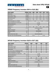
433 VF base output voltage set<br />
At [433]=60 Hz<br />
[356]=100%<br />
For 200 to 240 V, patterns based on output voltage are<br />
shown below. (Corresponding settings for 400-480 volts<br />
input: multiply by 2).<br />
240<br />
220<br />
200<br />
Min-max alarm tolerance band graph<br />
Measured load samples<br />
Min-max tolerance band<br />
Max alarm limit<br />
Min alarm limit<br />
60.0Hz [355]<br />
Fig. 32 V/HZ curves with varying base voltages<br />
Max <strong>Speed</strong><br />
[433]=240<br />
[433]=220<br />
[433]=200<br />
When the output voltage is set higher than the input voltage,<br />
the max output voltage is limited to the max input voltage.<br />
511 Analogue input<br />
Selectable Functions for analogue input terminals (AIN)<br />
000: Forward run<br />
001: Reverse run<br />
002: Preset speed command 1<br />
003: Preset speed command 2<br />
004: Preset speed command 3<br />
005: Jog frequency command<br />
006: External Emergency stop(E.S.)<br />
007: Base block (b.b.)<br />
008: Switch to 2nd acceleration/ deceleration time<br />
009: Reset<br />
010: Up command<br />
011: Down command<br />
012: Control signal switch<br />
013: Communication mode. Disable – Enable.<br />
014: Acceleration/deceleration prohibit<br />
015: Master/Auxiliary speed switch<br />
016: PID function prohibit<br />
017: Analog frequency signal input (terminal AIN)<br />
018: PID feedback signal (terminal AIN)<br />
019: DC Brake signal<br />
1. AIN on TM2 are multi-function input terminals which<br />
can be set to the above 19 functions.<br />
2. [511] function description:<br />
[511]=000/001(Forward/ Reverse)<br />
Forward command ON sets the VSD running forward,<br />
while OFF stops the VSD. [521] factory default is forward<br />
command.<br />
Reverse command ON sets the VSD running reverse,<br />
While OFF, the VSD stops. [522] factory default is<br />
reverse command.<br />
If via different digital inputs both the commands Forward<br />
and Reverse are ON, the VSD will go in Stop<br />
mode.<br />
[511]=002 to 004 (Preset speed command 1 to 3)<br />
When run signal is applied and the selected external<br />
multi-function input terminal is on, the VSD will run at<br />
one of 8 preset speeds which are controlled by the status<br />
of the terminals. The corresponding speeds are programmed<br />
in parameters [362] to [348] as shown in the<br />
table below.<br />
[511]=005 (Jog frequency command)<br />
When run signal is applied and the selected external<br />
multi-function input terminal is on and set to Jog speed,<br />
the VSD will run according to [348] setting.<br />
<strong>Emotron</strong> AB 01-3993-01r3 Programming instructions and menu list 45