sy24inst2 - The Initiative Group
sy24inst2 - The Initiative Group
sy24inst2 - The Initiative Group
Create successful ePaper yourself
Turn your PDF publications into a flip-book with our unique Google optimized e-Paper software.
Rendamax<br />
Connecting terminals [23]<br />
<strong>The</strong> boiler power supply, the connecting terminals, the pump connection and the pump relay are<br />
all fitted on top of the boiler. <strong>The</strong> terminal strip is located under the cover, on the right hand side.<br />
2.3 Boiler control<br />
<strong>The</strong> principle employed for the Boiler Management Unit is as follows: <strong>The</strong> boiler begins operating<br />
on receipt of a heating demand. This heating demand is generated either:<br />
A if the measured supply temperature is lower than the desired temperature<br />
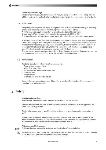
B as a result of “service operation” mode having been selected (W1 or W2)<br />
C in standby mode, when the water temperature falls below the frost protection temperature.<br />
After the unit has started up, the PID controller sends a signal to the fan, thus controlling the fan<br />
speed. Depending on the quantity of air displaced by the fan, the proportional pressure regulator<br />
will add the corresponding quantity of gas. In this way, the boiler power is continuously modulated,<br />
enabling the boiler to accurately follow the demand for heat. <strong>The</strong> fan is equipped with a<br />
speed feedback, enabling an even more accurate control behaviour.<br />
Once the supply water temperature exceeds the desired value, the unit will shut down. As soon as<br />
the supply water temperature falls below the set value, the boiler restarts.<br />
2.4 Safety aspects<br />
<strong>The</strong> boiler contains the following safety components:<br />
- Flame protection (1x re-start)<br />
- Water flow protection<br />
- Maximum water temperature protection<br />
- Gas valve test<br />
- Fan protection<br />
- Overload and underload protection.<br />
If one of these components operates, this results in a lockout fault. Lockout faults can only be<br />
cancelled by resetting the unit.<br />
3 Safety<br />
Installation instructions<br />
Read through these instructions carefully before starting the installation.<br />
<strong>The</strong> appliance must be installed by a recognised installer in accordance with the applicable national<br />
and local regulations.<br />
<strong>The</strong> installation may only be used for heating systems up to a maximum water temperature of<br />
90°C.<br />
It is expressly stated that these installation instructions must be seen as a supplement to the<br />
above mentioned standards and regulations and that these standards and regulations must take<br />
precedence over any information included in this technical manual.<br />
y<br />
w<br />
Pictograms used in this manual<br />
An instruction that is essential for the correct functioning of the installation.<br />
If these operations, procedures, etc., are not accurately followed this can result in serious damage<br />
to the installation, personal injury or environmental damage.<br />
Doc586/50CV22C 9


