sy24inst2 - The Initiative Group
sy24inst2 - The Initiative Group
sy24inst2 - The Initiative Group

You also want an ePaper? Increase the reach of your titles
YUMPU automatically turns print PDFs into web optimized ePapers that Google loves.
Rendamax<br />
d Ensure that the correct amount of high level ventilation exists<br />
e If the air supply is inadequate, it may be necessary to fit a mechanical means of providing adequate<br />
ventilation.<br />
5.3 Connections<br />
5.3.1 Gas connection<br />
<strong>The</strong> gas connection must be made by a recognised installer in accordance with the applicable<br />
national and local standards and regulations.<br />
<strong>The</strong> gas connection is made at the rear of the boiler.<br />
<strong>The</strong> pressure of the gas supplied to the unit must be reduced to 50 mbar for natural or for propane<br />
with the use of a gas pressure regulator.<br />
<strong>The</strong> loss of pressure in the connecting pipes must be such that, at maximum boiler capacity, the<br />
pressure must never fall below 17 mbar for natural gas or 30 mbar for propane.<br />
5.3.2 Electrical connection<br />
<strong>The</strong> electrical connections and provisions must comply with the applicable national and local<br />
standards and regulations.<br />
<strong>The</strong> units are wired in accordance with the electrical diagram supplied with the appliance.<br />
w<br />
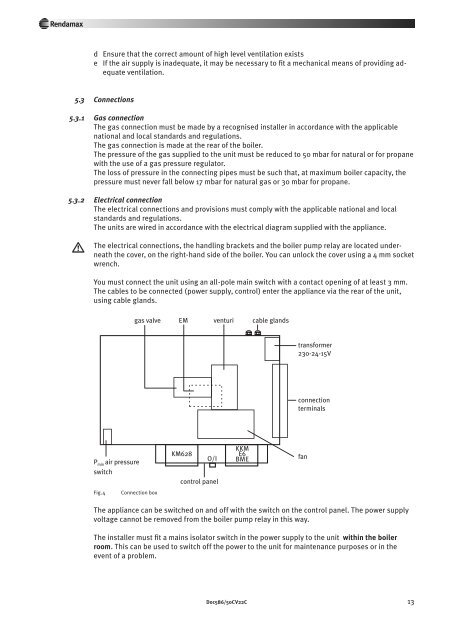
<strong>The</strong> electrical connections, the handling brackets and the boiler pump relay are located underneath<br />
the cover, on the right-hand side of the boiler. You can unlock the cover using a 4 mm socket<br />
wrench.<br />
You must connect the unit using an all-pole main switch with a contact opening of at least 3 mm.<br />
<strong>The</strong> cables to be connected (power supply, control) enter the appliance via the rear of the unit,<br />
using cable glands.<br />
gas valve EM venturi cable glands<br />
transformer<br />
230-24-15V<br />
connection<br />
terminals<br />
P min air pressure<br />
switch<br />
KM628<br />
O/I<br />
control panel<br />
KKM E6<br />
BME<br />
fan<br />
Fig.4<br />
Connection box<br />
<strong>The</strong> appliance can be switched on and off with the switch on the control panel. <strong>The</strong> power supply<br />
voltage cannot be removed from the boiler pump relay in this way.<br />
<strong>The</strong> installer must fit a mains isolator switch in the power supply to the unit within the boiler<br />
room. This can be used to switch off the power to the unit for maintenance purposes or in the<br />
event of a problem.<br />
Doc586/50CV22C 13