sy24inst2 - The Initiative Group
sy24inst2 - The Initiative Group
sy24inst2 - The Initiative Group

You also want an ePaper? Increase the reach of your titles
YUMPU automatically turns print PDFs into web optimized ePapers that Google loves.
Rendamax<br />
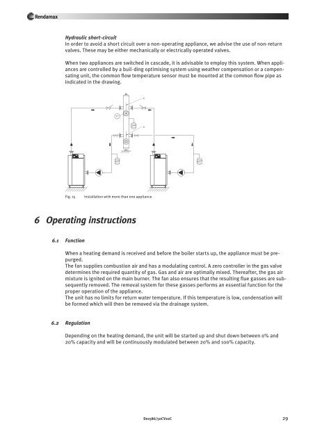
Hydraulic short-circuit<br />
In order to avoid a short circuit over a non-operating appliance, we advise the use of non-return<br />
valves. <strong>The</strong>se may be either mechanically or electrically operated valves.<br />
When two appliances are switched in cascade, it is advisable to employ this system. When appliances<br />
are controlled by a buil-ding optimising system using weather compensation or a compensating<br />
unit, the common flow temperature sensor must be mounted at the common flow pipe as<br />
indicated in the drawing.<br />
Fig. 15<br />
Installation with more than one appliance<br />
6 Operating instructions<br />
6 .1 Function<br />
When a heating demand is received and before the boiler starts up, the appliance must be prepurged.<br />
<strong>The</strong> fan supplies combustion air and has a modulating control. A zero controller in the gas valve<br />
determines the required quantity of gas. Gas and air are optimally mixed. <strong>The</strong>reafter, the gas air<br />
mixture is ignited on the main burner. <strong>The</strong> fan also ensures that the resulting flue gasses are subsequently<br />
removed. <strong>The</strong> removal system for these gasses performs an essential function for the<br />
proper operation of the appliance.<br />
<strong>The</strong> unit has no limits for return water temperature. If this temperature is low, condensation will<br />
be formed which will then be removed via the drainage system.<br />
6 .2 Regulation<br />
Depending on the heating demand, the unit will be started up and shut down between 0% and<br />
20% capacity and will be continuously modulated between 20% and 100% capacity.<br />
Doc586/50CV22C 29