sy24inst2 - The Initiative Group
sy24inst2 - The Initiative Group
sy24inst2 - The Initiative Group

You also want an ePaper? Increase the reach of your titles
YUMPU automatically turns print PDFs into web optimized ePapers that Google loves.
Rendamax<br />
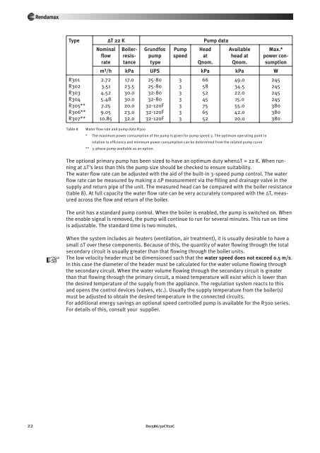
Type ∆T 22 K Pump data<br />
R301<br />
R302<br />
R303<br />
R304<br />
R305**<br />
R306**<br />
R307**<br />
Nominal<br />
flow<br />
rate<br />
Boilerresistance<br />
Grundfos<br />
pump<br />
type<br />
Pump<br />
speed<br />
Head<br />
at<br />
Qnom.<br />
Available<br />
head at<br />
Qnom.<br />
Max.*<br />
power consumption<br />
m 3 /h kPa UPS kPa kPa W<br />
2.72<br />
3.51<br />
4.52<br />
5.48<br />
7.25<br />
9.05<br />
10.85<br />
17.0<br />
23.5<br />
30.0<br />
30.0<br />
20.0<br />
23.0<br />
32.0<br />
25-80<br />
25-80<br />
32-80<br />
32-80<br />
32-120F<br />
32-120F<br />
32-120F<br />
3<br />
3<br />
3<br />
3<br />
3<br />
3<br />
3<br />
66<br />
58<br />
52<br />
45<br />
75<br />
65<br />
52<br />
49.0<br />
34.5<br />
22.0<br />
15.0<br />
55.0<br />
42.0<br />
20.0<br />
245<br />
245<br />
245<br />
245<br />
380<br />
380<br />
380<br />
Table 8<br />
Water flow rate and pump data R300<br />
* <strong>The</strong> maximum power consumption of the pump is given for pump speed 3. <strong>The</strong> optimum operating point in<br />
relation to efficiency and minimum power consumption can be determined from the related pump curve<br />
** 3-phase pump available as an option.<br />
<strong>The</strong> optional primary pump has been sized to have an optimum duty when∆T = 22 K. When running<br />
at ∆T’s less than this the pump size should be checked to ensure suitability.<br />
<strong>The</strong> water flow rate can be adjusted with the aid of the built-in 3-speed pump control. <strong>The</strong> water<br />
flow rate can be measured by making a ∆P measurement via the filling and drainage valve in the<br />
supply and return pipe of the unit. <strong>The</strong> measured head can be compared with the boiler resistance<br />
(table 8). At full capacity the water flow rate can be very accurately compared with the ∆T, measured<br />
across the flow and return of the boiler.<br />
<strong>The</strong> unit has a standard pump control. When the boiler is enabled, the pump is switched on. When<br />
the enable signal is removed, the pump will continue to run for several minutes. This run on time<br />
is adjustable. <strong>The</strong> standard time is two minutes.<br />
y<br />
When the system includes air heaters (ventilation, air treatment), it is usually desirable to have a<br />
small ∆T over these components. Because of this, the quantity of water flowing through the total<br />
secondary circuit is usually greater than that flowing through the boiler units.<br />
<strong>The</strong> low velocity header must be dimensioned such that the water speed does not exceed 0.5 m/s.<br />
In this case the diameter of the header must be calculated for the water volume flowing through<br />
the secondary circuit. When the water volume flowing through the secondary circuit is great er<br />
than that flowing through the primary circuit, a mixed temperature will exist which is lower than<br />
the desired temperature of the supply from the appliance. <strong>The</strong> regulation system reacts to this<br />
and opens the control devices (valves, etc.). Usually the supply temperature from the boiler(s)<br />
must be adjusted to obtain the desired temperature in the connected circuits.<br />
For additional energy savings an optional speed controlled pump is available for the R300 series.<br />
For details of this, consult your supplier.<br />
22 Doc586/50CV22C