

Nuts & Volts
Nuts & Volts
Nuts & Volts

Create successful ePaper yourself
Turn your PDF publications into a flip-book with our unique Google optimized e-Paper software.
QUESTIONS & ANSWERS<br />
I’M BUSY!<br />
QI have one land line phone<br />
service to my house that I<br />
share with the upstairs and<br />
my computer room in the<br />
basement. I have it connected so that if<br />
I want to go on to the Internet, I flip a<br />
switch that disconnects all the phones<br />
in the house and connects the line to<br />
my computer only. If the wife goes to use<br />
the phone and hears no dial tone, she<br />
knows I’m online. Works great — except<br />
for one problem — I can’t tell if she’s on<br />
the phone before I flip the switch (short<br />
of listening in on her conversation!). Is<br />
there a circuit (possibly LED) that will<br />
light when she is using the phone<br />
— Ted Petra<br />
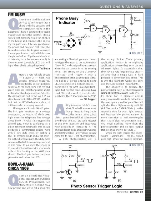
AHere’s a very reliable circuit<br />
— Figure 2 — that has<br />
several unique features.<br />
Specifically, it isn’t polarity<br />
sensitive to the phone line (the red and<br />
green wires are interchangeable) and it<br />
will run for about a year on two AA cells.<br />
This is thanks in part to the low 0.25 µA<br />
standby current of the 4093 IC, and the<br />
fact that the LED flashes for a short 16<br />
milliseconds once every second.<br />
All stages are Schmitt NAND gates.<br />
The first gate functions as a voltage<br />
comparator, the output of which goes<br />
high when the telephone line voltage<br />
drops below 15 volts. This triggers the<br />
second gate, which is configured as a<br />
pulse generator. Ordinarily, this design<br />
produces a symmetrical square wave<br />
with a 50% duty cycle. By adding a<br />
1N4148 steering diode and a 33K resistor<br />
in the discharge path, the duty cycle<br />
is lowered to 16% for an average current<br />
of less than 100 µA when the phone is<br />
in use (don’t email me with your math<br />
without first looking at the 4093 data<br />
sheet!). The final gate buffers the pulse<br />
generator and drives the LED.<br />
BOWL-A-RAMA<br />
CIRCA 1909<br />
QI am an electronics vocational<br />
teacher at the Orleans<br />
BOCES (Vocational). My<br />
students are working on a<br />
new project and we’ve hit a snag. We<br />
Phone Busy<br />
Indicator<br />
Phone<br />
Line<br />
are making a Skeeball game and I need<br />
to trigger the input to our Automation<br />
Direct PLC with a signal from a sensor<br />
when the ball drops into the scoring<br />
hole. I am trying to use a 2N3904<br />
transistor and trigger it with a<br />
photoresistor. I think our trouble is that<br />
the ball is 3” across and we’re using<br />
LEDs to shine on a CdS photocell. It<br />
works fine if the light is a small flashlight,<br />
but not the blue LEDs we have<br />
tried. We really want to use LEDs for<br />
reliability. The PLC operates at 24 VDC.<br />
— Bill Leggett<br />
ASilly to say — I didn’t know<br />
what Skeeball was — even<br />
though I used to hang out in<br />
arcades in my teens (circa<br />
1960). I guess Skeeball had fallen out of<br />
favor by that time. So I did some research<br />
on this 1909 invention and discovered<br />
your problem in recreating it. The<br />
original design used crosshair switches<br />
and latching relays (a very clever design/<br />
game for its time!), not photoresistors.<br />
A CdS photoresistive cell is<br />
LED<br />
2.2K<br />
1A<br />
200V<br />
1N5245A<br />
15V<br />
4.7M<br />
4.7M<br />
4093<br />
4093<br />
33K<br />
0.47<br />
1N4148<br />
4.7M<br />
+24V +24V<br />
10K<br />
(a)<br />
1K<br />
PLC<br />
2N2222<br />
4093<br />
+<br />
3V<br />
AA cells<br />
100<br />
LED<br />
the wrong choice. Their primary<br />
application (today) is in night/day<br />
applications where they turn on and<br />
off street lights. To accomplish this,<br />
they have a very large surface area —<br />
an area that a single LED is hard<br />
pressed to cover with any effect. This<br />
is why the flashlight works (full sun)<br />
and the LED doesn’t (moonlight).<br />
The answer is to replace the<br />
photoresistor with a phototransistor<br />
(www.allelectronics.com CAT# PTR-1).<br />
It’s about 1/4” in diameter and is<br />
easily recessed into a hole drilled into<br />
the wood/plastic wall of your Skeeball<br />
cylinder. Use a high-intensity red LED<br />
(All Electronics CAT# LED-94 ) on the<br />
opposite side for your light source;<br />
red because the phototransistor is<br />
more sensitive to red wavelengths<br />
than it is to blue. For the circuit itself,<br />
you need nothing more than the<br />
phototransistor and an NPN output<br />
transistor as shown in Figure 3.<br />
When the light strikes the photosensor<br />
— version (a) — the PLC output<br />
goes high. When the beam is interrupt-<br />
LED<br />
2.2K<br />
10K<br />
10K<br />
(b)<br />
Photo Sensor Trigger Logic<br />
1K<br />
PLC<br />
2N2222<br />
■ FIGURE 2<br />
■ FIGURE 3<br />
March 2006 21


