

Nuts & Volts
Nuts & Volts
Nuts & Volts

Create successful ePaper yourself
Turn your PDF publications into a flip-book with our unique Google optimized e-Paper software.
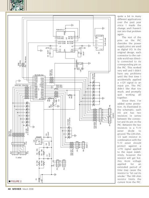
■ FIGURE 2<br />
quite a bit in many<br />
different applications<br />
over the past year<br />
since I made the<br />
change, and I haven’t<br />
run into that problem<br />
again.<br />
The rest of the<br />
pins on the PIC<br />
(besides the power<br />
supply pins) are used<br />
as digital I/O. In the<br />
original design, each<br />
connector to the outside<br />
world was directly<br />
connected to its<br />
corresponding pin on<br />
the PIC. This worked<br />
very well and I didn’t<br />
have any problems<br />
until the first time I<br />
accidentally applied<br />
a +12V signal to an<br />
input pin. The PIC<br />
didn’t like that too<br />
much, and promptly<br />
quit working all<br />
together.<br />
Since then, I’ve<br />
added some protection.<br />
As illustrated in<br />
the schematic, each<br />
I/O pin has two<br />
resistors in series<br />
between the connector<br />
and its pin on the<br />
PIC. Between the two<br />
resistors is a 5.1V<br />
zener diode to<br />
ground. The 220 ohm,<br />
1/2 watt resistor in<br />
combination with the<br />
5.1V zener should<br />
protect against a<br />
+15V signal applied<br />
to the input indefinitely,<br />
however the<br />
resistor will get hot.<br />
Any more voltage<br />
applied for an<br />
extended period of<br />
time may cause the<br />
resistor to “let out its<br />
smoke.” The 100 ohm<br />
resistor limits the<br />
current from the PIC,<br />
40 March 2006


