

Nuts & Volts
Nuts & Volts
Nuts & Volts

Create successful ePaper yourself
Turn your PDF publications into a flip-book with our unique Google optimized e-Paper software.
The Sound Lab Mini-Synth Sound Synthesizer<br />
cut-off frequency of the VCF. S8<br />
switches the LFO control voltage on<br />
or off. When on, the level of the LFO<br />
output pot determines how much the<br />
LFO controls the cut-off frequency of<br />
the VCF. R37 controls the initial<br />
cut-off frequency of the VCF. When S7<br />
or S8 is on, it is best to turn R37 off or<br />
nearly off.<br />
Voltage-Controlled<br />
Oscillators<br />
The oscillators are the heart of<br />
any synthesizer and they provide the<br />
main sound generating capability<br />
(see Figure 5). Just about every sound<br />
you hear has some pitch to it — a<br />
voice, a trumpet, an airplane, etc. The<br />
pitch may be modulated or modified,<br />
but it is there a great majority of the<br />
time.<br />
The Sound Lab uses two voltage<br />
controlled ramp oscillators to provide<br />
pitch sources. IC5-B and IC5-A and<br />
associated transistors and components<br />
comprise a linear voltage to<br />
logarithmic current converter. The<br />
control voltages that are summed by<br />
IC5-B range from -8 to 8 volts. The<br />
resulting current ranges from around<br />
1 µA to 1 mA and, since the oscillators<br />
go up approximately one octave every<br />
time the current doubles, this gives<br />
the oscillator a nice range from a subaudible<br />
0.6 Hz to about 8.3 kHz.<br />
Oscillation occurs because as the<br />
current is pulled out of the input of<br />
integrator IC5-D, its output goes high<br />
until IC5-C (comparator with hysteresis)<br />
pin 8 goes high and shorts the<br />
integrating capacitor (C8), which<br />
causes the cycle to begin anew and<br />
subsequently repeat. IC6 is used in a<br />
8.1 in.<br />
similar configuration.<br />
The output of IC6-D (point ZZ) is<br />
fed into comparator IC2-A in order to<br />
provide a square/pulse wave shaper<br />
for Oscillator 2. The control voltage<br />
fed into IC2-A pin 2 via resistors R86<br />
and R87 determines the comparator<br />
threshold and thus the point at which<br />
the output (pin 1) goes high and low.<br />
Varying R85 will change the pulse<br />
width and vary the timbre of<br />
Oscillator 2 when Rect Wave is<br />
selected. S15 permits the LFO output<br />
voltage to modulate the pulse width,<br />
which can cause the output of<br />
Oscillator 2 to sound like two<br />
oscillators tuned very close together<br />
(when approximately 1 Hz LFO<br />
frequency is used).<br />
S11, S13, S12, and S14 are used<br />
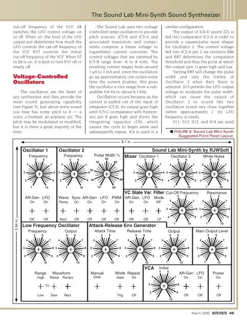
■ FIGURE 6. Sound Lab Mini-Synth<br />
Suggested Front Panel Layout.<br />
Oscillator 1<br />
Frequency<br />
4<br />
3<br />
5 6<br />
7<br />
8<br />
Oscillator 2<br />
Frequency<br />
5 6<br />
40<br />
4<br />
7<br />
30<br />
3<br />
8<br />
Pulse Width %<br />
50<br />
Mixer<br />
Oscillator 1<br />
Sound Lab Mini-Synth by RJWSoft<br />
Oscillator 2<br />
White Noise<br />
5 6<br />
5 6<br />
5 6<br />
60<br />
4<br />
7 4<br />
7 4<br />
7<br />
70<br />
3<br />
8 3<br />
8 3<br />
8<br />
2<br />
9<br />
2<br />
9<br />
20<br />
80<br />
2<br />
9<br />
2<br />
9<br />
2<br />
9<br />
1<br />
10 1<br />
10 10 90<br />
1<br />
AR-Gen LFO Wave Sync AR-Gen LFO PWM<br />
On On Ramp On On On On<br />
10 1<br />
VC State Var. Filter<br />
AR-Gen<br />
On<br />
LFO<br />
On<br />
Mode<br />
BP<br />
4<br />
5 6<br />
10 1<br />
Cut-Off Frequency<br />
7<br />
4<br />
10<br />
Resonance<br />
5 6<br />
7<br />
3<br />
8<br />
3<br />
8<br />
5.94 in.<br />
Off Off Rect Off Off Off Off Off Off LP<br />
1 10 1 10<br />
Low Frequency Oscillator Attack-Release Env Generator<br />
Frequency Output Attack Time Release Time Output Main Output Level<br />
5 6<br />
5 6<br />
5 6<br />
5 6<br />
5 6<br />
5 6<br />
4<br />
7 4<br />
7 4<br />
7 4<br />
7 4<br />
7 4<br />
7<br />
2<br />
9<br />
2<br />
9<br />
3<br />
8 3<br />
8<br />
3<br />
8<br />
3<br />
8<br />
3<br />
8<br />
3<br />
8<br />
2<br />
9<br />
2<br />
9<br />
2<br />
9<br />
2<br />
9<br />
2<br />
9<br />
2<br />
9<br />
1<br />
10<br />
Range<br />
High<br />
1<br />
Waveform<br />
Ramp Ramps<br />
10<br />
1<br />
Manual<br />
Gate<br />
10<br />
Mode<br />
Gate<br />
1<br />
Repeat<br />
On<br />
10<br />
VCA<br />
4<br />
1<br />
Initial<br />
5 6<br />
7<br />
10<br />
AR-Gen<br />
On<br />
1<br />
LFO<br />
On<br />
10<br />
Power<br />
On<br />
Tri<br />
3<br />
8<br />
Low<br />
Saw<br />
Rect<br />
Trig<br />
Off<br />
2<br />
1<br />
10<br />
9<br />
Off<br />
Off<br />
Off<br />
March 2006 49


