Cooper B-Line Pipe Hangers & Supports - Dixie Construction Products
Cooper B-Line Pipe Hangers & Supports - Dixie Construction Products
Cooper B-Line Pipe Hangers & Supports - Dixie Construction Products

You also want an ePaper? Increase the reach of your titles
YUMPU automatically turns print PDFs into web optimized ePapers that Google loves.
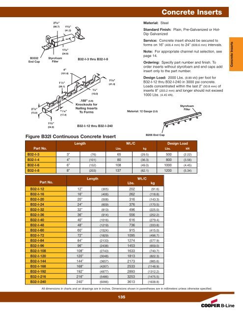
Concrete Inserts<br />
2 5 /8”<br />
(66.7)<br />
1 5 /8”<br />
(41.3)<br />
Material: Steel<br />
Standard Finish: Plain, Pre-Galvanized or Hot-<br />
Dip Galvanized<br />
B3332<br />
End Cap<br />
Styrofoam<br />
Filler<br />
1 3 /8”<br />
(34.9)<br />
4”<br />
(101.6)<br />
1 1 /2”<br />
(38.1)<br />
B32-I-3 thru B32-I-8<br />
3/4”<br />
(19.0)<br />
1 5 /8”<br />
(41.3)<br />
Service: Concrete insert should be secured to<br />
forms on 16” (406.4 mm) to 24” (609.6 mm) intervals.<br />
Note: For appropriate channel nut selection, see<br />
page 14.<br />
Ordering: Specify part number and finish. To<br />
order inserts without styrofoam and end caps add<br />
insert only to the part number.<br />
Design Load: 2000 Lbs. (8.89 kN) per foot for<br />
B32-I-12 thru B32-I-240 in 3000 psi concrete.<br />
Loads concentrated within the last 2” (50.8 mm) of<br />
inserts 8” (203.2 mm) and longer should not exceed<br />
1000 Lbs. (4.45 kN).<br />
Concrete Inserts<br />
2 7 /8”<br />
(73.0)<br />
11/16”<br />
(17.4)<br />
.188” (4.8)<br />
Knockouts for<br />
Nailing Inserts<br />
To Forms<br />
Material: 12 Gauge (2.6)<br />
Styrofoam<br />
Filler<br />
1 3 /8”<br />
(34.9)<br />
B32-I-12 thru B32-I-240<br />
Figure B32I Continuous Concrete Insert<br />
B206 End Cap<br />
Length Wt./C Design Load<br />
Part No. Lbs. kg Lbs. kN<br />
B32-I-3 3” (76) 65 (29.5) 500 (2.22)<br />
B32-I-4 4” (101) 80 (36.3) 800 (3.56)<br />
B32-I-6 6” (152) 108 (49.0) 1000 (4.45)<br />
B32-I-8 8” (203) 137 (62.1) 1200 (5.34)<br />
Length<br />
Wt./C<br />
Part No. Lbs. kg<br />
B32-I-12 12” (305) 202 (91.6)<br />
B32-I-16 16” (406) 262 (118.8)<br />
B32-I-20 20” (508) 316 (143.3)<br />
B32-I-24 24” (609) 376 (170.5)<br />
B32-I-32 32” (813) 496 (225.0)<br />
B32-I-36 36” (914) 556 (252.2)<br />
B32-I-40 40” (1016) 616 (279.4)<br />
B32-I-48 48” (1219) 736 (333.8)<br />
B32-I-60 60” (1524) 915 (415.0)<br />
B32-I-72 72” (1829) 1095 (496.7)<br />
B32-I-84 84” (2133) 1274 (577.9)<br />
B32-I-96 96” (2438) 1453 (659.0)<br />
B32-I-108 108” (2743) 1633 (740.7)<br />
B32-I-120 120” (3048) 1813 (822.3)<br />
B32-I-144 144” (3657) 2173 (985.6)<br />
B32-I-168 168” (4267) 2533 (1148.9)<br />
B32-I-192 192” (4877) 2893 (1312.2)<br />
B32-I-216 216” (5486) 3253 (1475.5)<br />
B32-I-240 240” (6096) 3613 (1638.8)<br />
All dimensions in charts and on drawings are in inches. Dimensions shown in parentheses are in millimeters unless otherwise specified.<br />
135