Cooper B-Line Pipe Hangers & Supports - Dixie Construction Products
Cooper B-Line Pipe Hangers & Supports - Dixie Construction Products
Cooper B-Line Pipe Hangers & Supports - Dixie Construction Products

Create successful ePaper yourself
Turn your PDF publications into a flip-book with our unique Google optimized e-Paper software.
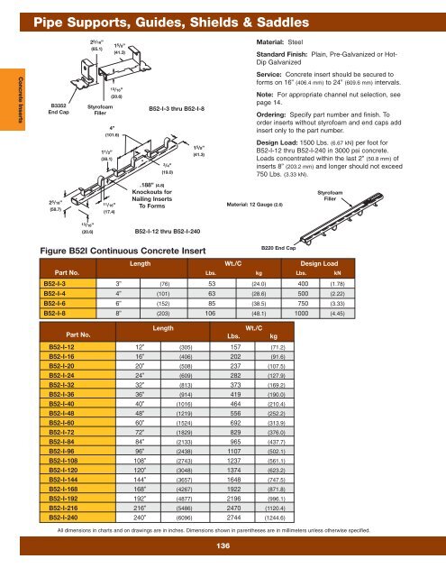
<strong>Pipe</strong> <strong>Supports</strong>, Guides, Shields & Saddles<br />
2 9 /16”<br />
(65.1)<br />
1 5 /8”<br />
(41.3)<br />
Material: Steel<br />
Standard Finish: Plain, Pre-Galvanized or Hot-<br />
Dip Galvanized<br />
Concrete Inserts<br />
B3352<br />
End Cap<br />
Styrofoam<br />
Filler<br />
1 1 /2”<br />
(38.1)<br />
13/16”<br />
(20.6)<br />
4”<br />
(101.6)<br />
B52-I-3 thru B52-I-8<br />
3/4”<br />
(19.0)<br />
1 5 /8”<br />
(41.3)<br />
Service: Concrete insert should be secured to<br />
forms on 16” (406.4 mm) to 24” (609.6 mm) intervals.<br />
Note: For appropriate channel nut selection, see<br />
page 14.<br />
Ordering: Specify part number and finish. To<br />
order inserts without styrofoam and end caps add<br />
insert only to the part number.<br />
Design Load: 1500 Lbs. (6.67 kN) per foot for<br />
B52-I-12 thru B52-I-240 in 3000 psi concrete.<br />
Loads concentrated within the last 2” (50.8 mm) of<br />
inserts 8” (203.2 mm) and longer should not exceed<br />
750 Lbs. (3.33 kN).<br />
2 5 /16”<br />
(58.7)<br />
11/16”<br />
(17.4)<br />
.188” (4.8)<br />
Knockouts for<br />
Nailing Inserts<br />
To Forms<br />
Material: 12 Gauge (2.6)<br />
Styrofoam<br />
Filler<br />
13/16”<br />
(20.6)<br />
B52-I-12 thru B52-I-240<br />
Figure B52I Continuous Concrete Insert<br />
136<br />
B220 End Cap<br />
Length Wt./C Design Load<br />
Part No. Lbs. kg Lbs. kN<br />
B52-I-3 3” (76) 53 (24.0) 400 (1.78)<br />
B52-I-4 4” (101) 63 (28.6) 500 (2.22)<br />
B52-I-6 6” (152) 85 (38.5) 750 (3.33)<br />
B52-I-8 8” (203) 106 (48.1) 1000 (4.45)<br />
Length<br />
Wt./C<br />
Part No. Lbs. kg<br />
B52-I-12 12” (305) 157 (71.2)<br />
B52-I-16 16” (406) 202 (91.6)<br />
B52-I-20 20” (508) 237 (107.5)<br />
B52-I-24 24” (609) 282 (127.9)<br />
B52-I-32 32” (813) 373 (169.2)<br />
B52-I-36 36” (914) 419 (190.0)<br />
B52-I-40 40” (1016) 464 (210.4)<br />
B52-I-48 48” (1219) 556 (252.2)<br />
B52-I-60 60” (1524) 692 (313.9)<br />
B52-I-72 72” (1829) 829 (376.0)<br />
B52-I-84 84” (2133) 965 (437.7)<br />
B52-I-96 96” (2438) 1107 (502.1)<br />
B52-I-108 108” (2743) 1237 (561.1)<br />
B52-I-120 120” (3048) 1374 (623.2)<br />
B52-I-144 144” (3657) 1648 (747.5)<br />
B52-I-168 168” (4267) 1922 (871.8)<br />
B52-I-192 192” (4877) 2196 (996.1)<br />
B52-I-216 216” (5486) 2470 (1120.4)<br />
B52-I-240 240” (6096) 2744 (1244.6)<br />
All dimensions in charts and on drawings are in inches. Dimensions shown in parentheses are in millimeters unless otherwise specified.