Engineering Design Manual - Loudoun Water
Engineering Design Manual - Loudoun Water
Engineering Design Manual - Loudoun Water
You also want an ePaper? Increase the reach of your titles
YUMPU automatically turns print PDFs into web optimized ePapers that Google loves.
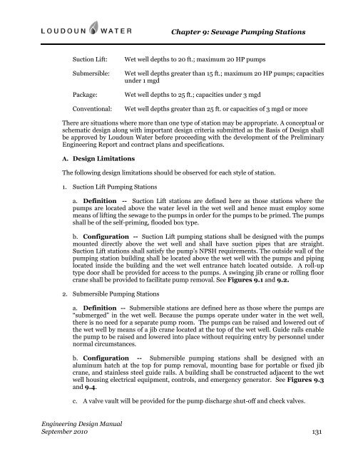
Chapter 9: Sewage Pumping Stations<br />
Suction Lift:<br />
Submersible:<br />
Package:<br />
Conventional:<br />
Wet well depths to 20 ft.; maximum 20 HP pumps<br />
Wet well depths greater than 15 ft.; maximum 20 HP pumps; capacities<br />
under 1 mgd<br />
Wet well depths to 25 ft.; capacities under 3 mgd<br />
Wet well depths greater than 25 ft. or capacities of 3 mgd or more<br />
There are situations where more than one type of station may be appropriate. A conceptual or<br />
schematic design along with important design criteria submitted as the Basis of <strong>Design</strong> shall<br />
be approved by <strong>Loudoun</strong> <strong>Water</strong> before proceeding with the development of the Preliminary<br />
<strong>Engineering</strong> Report and contract plans and specifications.<br />
A. <strong>Design</strong> Limitations<br />
The following design limitations should be observed for each style of station.<br />
1. Suction Lift Pumping Stations<br />
a. Definition -- Suction Lift stations are defined here as those stations where the<br />
pumps are located above the water level in the wet well and hence must employ some<br />
means of lifting the sewage to the pumps in order for the pumps to be primed. The pumps<br />
shall be of the self-priming, flooded box type.<br />
b. Configuration -- Suction Lift pumping stations shall be designed with the pumps<br />
mounted directly above the wet well and shall have suction pipes that are straight.<br />
Suction Lift stations shall satisfy the pump’s NPSH requirements. The outside wall of the<br />
pumping station building shall be located above the wet well with the pumps and piping<br />
located inside the building and the wet well entrance hatch located outside. A roll-up<br />
type door shall be provided for access to the pumps. A swinging jib crane or rolling floor<br />
crane shall be provided to facilitate pump removal. See Figures 9.1 and 9.2.<br />
2. Submersible Pumping Stations<br />
a. Definition -- Submersible stations are defined here as those where the pumps are<br />
“submerged” in the wet well. Because the pumps operate under water in the wet well,<br />
there is no need for a separate pump room. The pumps can be raised and lowered out of<br />
the wet well by means of a jib crane located at the top of the wet well. Guide rails enable<br />
the pump to be raised and lowered into place without requiring entry by personnel under<br />
normal circumstances.<br />
b. Configuration -- Submersible pumping stations shall be designed with an<br />
aluminum hatch at the top for pump removal, mounting base for portable or fixed jib<br />
crane, and stainless steel guide rails. A building shall be constructed adjacent to the wet<br />
well housing electrical equipment, controls, and emergency generator. See Figures 9.3<br />
and 9.4.<br />
c. A valve vault will be provided for the pump discharge shut-off and check valves.<br />
<strong>Engineering</strong> <strong>Design</strong> <strong>Manual</strong><br />
September 2010 131


