Engineering Design Manual - Loudoun Water
Engineering Design Manual - Loudoun Water
Engineering Design Manual - Loudoun Water
Create successful ePaper yourself
Turn your PDF publications into a flip-book with our unique Google optimized e-Paper software.
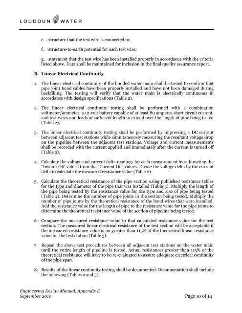
e. structure that the test wire is connected to;<br />
f. structure-to-earth potential for each test wire;<br />
g. statement that the test wire has been installed properly in accordance with the criteria<br />
listed above. Data shall be maintained for inclusion in the final quality assurance report.<br />
B. Linear Electrical Continuity<br />
1. The linear electrical continuity of the bonded water main shall be tested to confirm that<br />
pipe joint bond cables have been properly installed and have not been damaged during<br />
backfilling. The testing will verify that the water main is electrically continuous in<br />
accordance with design specifications (Table 2).<br />
2. The linear electrical continuity testing shall be performed with a combination<br />
voltmeter/ammeter, a 12-volt battery capable of at least 80 amperes short circuit current,<br />
and test wires and leads of sufficient length to extend over the length of pipe being tested<br />
(Table 2).<br />
3. The linear electrical continuity testing shall be performed by impressing a DC current<br />
between adjacent test stations while simultaneously measuring the resultant voltage drop<br />
on the pipeline between the adjacent test stations. Voltage and current measurements<br />
shall be recorded with the current applied and immediately after the current is turned off<br />
(Table 2).<br />
4. Calculate the voltage and current delta readings for each measurement by subtracting the<br />
"Instant Off' values from the "Current On" values. Divide the voltage delta by the current<br />
delta to calculate the measured resistance value (Table 2).<br />
5. Calculate the theoretical resistance of the pipe section using published resistance tables<br />
for the type and diameter of the pipe that was installed (Table 3). Multiply the length of<br />
the pipe being tested by the resistance value for the type and size of pipe being tested<br />
(Table 4). Determine the number of pipe joints in the section being tested. Multiply the<br />
number of pipe joints by the theoretical resistance of the bond wires that were installed.<br />
Add the resistance value for the length of pipe to the resistance value for the pipe joints to<br />
determine the theoretical resistance value of the section of pipeline being tested.<br />
6. Compare the measured resistance value to that calculated resistance value for the test<br />
section. The measured linear electrical resistance of the test section will be acceptable if<br />
the measured resistance value is no greater than 115% of the theoretical linear resistance<br />
value for the test station (Table 3).<br />
7. Repeat the above test procedures between all adjacent test stations on the water main<br />
until the entire length of pipeline is tested. Actual resistances greater than 115% of the<br />
theoretical resistance will have to be re-evaluated to assure adequate electrical continuity<br />
of the pipe span.<br />
8. Results of the linear continuity testing shall be documented. Documentation shall include<br />
the following (Tables 2 and 3):<br />
<strong>Engineering</strong> <strong>Design</strong> <strong>Manual</strong>, Appendix E<br />
September 2010 Page 10 of 14


