Engineering Design Manual - Loudoun Water
Engineering Design Manual - Loudoun Water
Engineering Design Manual - Loudoun Water

You also want an ePaper? Increase the reach of your titles
YUMPU automatically turns print PDFs into web optimized ePapers that Google loves.
Chapter 9: Sewage Pumping Stations<br />
shall be arranged so as to independently ventilate all of the wells and/or vaults at the<br />
station. Dry well supply and exhaust louvers shall have insect screens. Exhaust air shall<br />
be drawn from the lowest floor or area of the structure. Supply air will enter at the top<br />
floor or area. No damper shall be used on the exhaust or fresh air ducts, and the screens<br />
will be ¼-inch stainless steel. The switches for the operation of the ventilation<br />
equipment shall be well marked and located above grade near the entrance doors or<br />
hatches. The lighting and ventilation switches on all wet wells shall be interlocking. If 3-<br />
phase service is available, the exhaust fan motors shall be 3-phase motors. Time clock<br />
switches will be provided to allow a programmed run time of the exhaust fans. There will<br />
be no interconnection between the ventilation systems in the wet well and dry well. Dry<br />
well entrances shall not be in close proximity to the wet well or generator exhausts.<br />
3. Wet wells ventilation may be either continuous or intermittent. Ventilation, if<br />
continuous, shall provide at least 12 complete air changes per hour; if intermittent, at<br />
least 30 complete air changes per hour. Wet well ventilation fans and ducts shall be<br />
constructed of either stainless steel or fiberglass.<br />
4. Dry well ventilation may be either continuous or intermittent. Ventilation, if continuous,<br />
shall provide at least 6 complete air changes per hour; if intermittent, at least 30<br />
complete air changes per hour.<br />
5. Ventilation openings shall be protected with aluminum louvers with bird-screens.<br />
O. <strong>Water</strong> Supply<br />
1. Wherever possible, public water will be extended to the pumping station for wash down<br />
and cleanup operations. The water service into the station will be a 1-inch, type “K”<br />
copper. A fire hydrant shall be provided on site. The meter will be set as shown in the<br />
details of this manual. If public water is not available, a well will be provided at the site.<br />
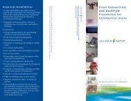
2. Appropriate cross connection measures shall be used to ensure that no physical<br />
connection exists between any potable water supply and a sewage pumping station that<br />
under any conditions might cause a contamination of the potable water supply. A non<br />
freeze yard hydrant will be installed at the station. A 50 foot long, 1-inch diameter hose<br />
and a hose rack will be provided at the control building. When required, restroom<br />
facilities will be provided at pumping stations.<br />
P. Vaults<br />
1. Access hatches will be located in the vault so as to facilitate the removal of the pump’s,<br />
motor and other equipment in the station without disrupting the operation of the facility.<br />
2. All hatches will be aluminum with stainless steel hardware. All hatches will have locking<br />
hasps and automatic hold-open arms with safety grates.<br />
3. A fixed or portable hoist suitable for removing the comminutor, pumps and other<br />
equipment will be provided at the vault. If a portable hoist is provided, surface mount<br />
sockets will be installed at the comminutor vault and pump well.<br />
<strong>Engineering</strong> <strong>Design</strong> <strong>Manual</strong><br />
September 2010 148