


You also want an ePaper? Increase the reach of your titles
YUMPU automatically turns print PDFs into web optimized ePapers that Google loves.
LEGEND HEATERS<br />
SERVICE WORKBOOK<br />
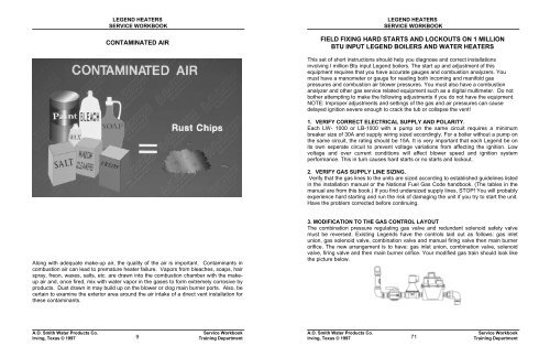
CONTAMINATED AIR<br />
LEGEND HEATERS<br />
SERVICE WORKBOOK<br />
FIELD FIXING HARD STARTS AND LOCKOUTS ON 1 MILLION<br />
BTU INPUT LEGEND BOILERS AND WATER HEATERS<br />
This set of short instructions should help you diagnose and correct installations<br />
involving I million Btu input Legend boilers. The start up and adjustment of this<br />
equipment requires that you have accurate gauges and combustion analyzers. You<br />
must have a manometer or gauge for reading both incoming and manifold gas<br />
pressures and combustion air blower pressures. You must also have a combustion<br />
analyzer and other gas service related equipment such as a digital multimeter. Do not<br />
bother attempting to make the following adjustments if you do not have the equipment.<br />
NOTE: Improper adjustments and settings of the gas and air pressures can cause<br />
delayed ignition severe enough to crack the tub or collapse the vent!<br />
1. VERIFY CORRECT ELECTRICAL SUPPLY AND POLARITY.<br />
Each LW- 1000 or LB-1000 with a pump on the same circuit requires a minimum<br />
breaker size of 30A and supply wiring sized accordingly. For a boiler without a pump on<br />
the same circuit, the rating should be 15A. It is very important that each Legend be on<br />
its own seperate circuit to prevent voltage variations from affecting the ignition. Low<br />
voltage and over current conditions will affect blower speed and ignition system<br />
performance. This in turn causes hard starts or no starts and lockout.<br />
2. VERIFY GAS SUPPLY LINE SIZING.<br />
Verify that the gas lines to the units are sized according to established guidelines listed<br />
in the installation manual or the National Fuel Gas Code handbook. (The tables in the<br />
manual are from this book.) If you find undersized supply lines, STOP! You will probably<br />
experience hard starting and run the risk of damaging the unit if you try to start the unit.<br />
Have the problem corrected before continuing.<br />
Along with adequate make-up air, the quality of the air is important. Contaminants in<br />
combustion air can lead to premature heater failure. Vapors from bleaches, soaps, hair<br />
spray, freon, waxes, salts, etc. are drawn into the combustion chamber with the makeup<br />
air and, once fired, mix with water vapor in the gases to form extremely corrosive by<br />
products. Dust drawn in may build up on the blower or clog main burner ports. Also, be<br />
certain to examine the exterior area around the air intake of a direct vent installation for<br />
these contaminants.<br />
3. MODIFICATION TO THE GAS CONTROL LAYOUT<br />
The combination pressure regulating gas valve and redundant solenoid safety valve<br />
must be reversed. Existing Legends have the controls laid out as follows: gas inlet<br />
union, gas solenoid valve, combination valve and manual firing valve then main burner<br />
orifice. The new arrangement is to have: gas inlet union, combination valve, solenoid<br />
valve, firing valve and then main burner orifice. Your modified gas train should look like<br />
the picture below.<br />
A.O. <strong>Smith</strong> <strong>Water</strong> Products Co.<br />
Irving, Texas © 1997<br />
9<br />
Service Workbook<br />
Training Department<br />
A.O. <strong>Smith</strong> <strong>Water</strong> Products Co.<br />
Irving, Texas © 1997<br />
71<br />
Service Workbook<br />
Training Department


