


Create successful ePaper yourself
Turn your PDF publications into a flip-book with our unique Google optimized e-Paper software.
LEGEND 1HEATERS<br />
SERVICE WORKBOOK<br />
LEGEND WORKBOOK TABLE OF CONTENT<br />
PAGE PAGE<br />
Introduction..................................... 2<br />
Tools/Terms ................................... 3<br />
Installation<br />
Clearances ..................................... 4<br />
Air Requirements............................ 6<br />
Contaminated Air............................ 9<br />
Flammable ................................... 10<br />
Gas Pressure ............................... 11<br />
LW1000 Air Shutter Adjustment... 14<br />
Venting ......................................... 15<br />
Sequence of Operation<br />
Mechanical ................................... 18<br />
Troubleshooting<br />
Preliminary Checks ...................... 19<br />
Polarity Check .............................. 20<br />
HSI-120 VAC Supply.................... 21<br />
Transformer-24 VAC.................... 22<br />
HSI-24 VAC Supply...................... 23<br />
System Control............................. 24<br />
Operating Control ......................... 25<br />
HSI - Terminal 9 ........................... 26<br />
HSI - Terminal 1 ........................... 27<br />
1R Relay....................................... 28<br />
Circulating Pump.......................... 30<br />
2R Relay....................................... 32<br />
Troubleshooting (continued)<br />
Air Blower......................................34<br />
<strong>Water</strong> Flow Switch ........................35<br />
High Limit ......................................36<br />
Blower Prover Switch....................37<br />
Low Gas Pressure Switch.............38<br />
Blocked Flue Switch......................39<br />
HSI Terminal 8..............................40<br />
HSI Terminal 2..............................41<br />
Ignitor Test....................................42<br />
2R Relay .......................................44<br />
3 R Relay LW/LB 1000 .................47<br />
Blower Speed................................50<br />
HSI - Terminal 1............................51<br />
3R Relay-LW/LB 1000 ..................52<br />
Gas Valve - Voltage ......................53<br />
Misc. Tables ....................................55<br />
Wiring Diagrams............................56<br />
I.R.I. Information............................58<br />
Spacer Kit - LW/LB 1000..........70<br />
Gas Train Model LW/LB 1000 . 71<br />
Orifice Tables .................................74<br />
General Q & A.................................75<br />
Misc. Service Notes .....................76<br />
Maintenance....................................78<br />
LEGEND WORKBOOK INTRODUCTION<br />
This service workbook is designed to aid in servicing and troubleshooting A.O. <strong>Smith</strong> Legend Hot <strong>Water</strong><br />
Supply Boilers in the field. No duplication or reproduction of this book may be made without the express<br />
written authorization of the A.O. <strong>Smith</strong> <strong>Water</strong> Products Company.<br />
The following text and illustrations will provide you with a step by step procedure to verify proper<br />
installation, operation, and troubleshooting procedures. Additional quick reference date is included to<br />
assist you in servicing this product.<br />
The information contained in this workbook is designed to answer commonly faced situations encountered<br />
in the operation of the Legend product line and is not meant to be all inclusive. If you are experiencing a<br />
problem not covered in this workbook, please contact the A.O. <strong>Smith</strong> Technical Information Department at<br />
1-800-527-1953 or your local A.O. <strong>Smith</strong> <strong>Water</strong> Products Company representative for further assistance.<br />
This workbook is intended for use by licensed plumbing professionals and reference should be made to<br />
the installation manual accompanying the product. This workbook contains supplemental information to<br />
the Legend installation and operation manual.<br />
A.O. <strong>Smith</strong> <strong>Water</strong> Products Co.<br />
Irving, Texas © 1997<br />
1<br />
Service Workbook<br />
Training Department
LEGEND HEATERS<br />
SERVICE WORKBOOK<br />
Maintenance – See instruction manual more detailed information<br />
Function Instructions Time<br />
Burner Check Check flame characteristics Every 6 months<br />
Condensate Tubes<br />
Delime<br />
Electrical Connections<br />
Light Off<br />
Pressure Relief Valve<br />
Pressure and<br />
Temperature Relief<br />
Valve<br />
Pressure Switches<br />
Check that they are tightly connected and free<br />
to operate<br />
Check for an increase of approximately 5°F in<br />
the temperature rise (verse the “clean”<br />
temperature rise) through the Legend. Do Not<br />
allow a heavy build of lime in this heater. The<br />
water passages cannot be individually<br />
delimed.<br />
Power OFF. Feel for loose wire connections or<br />
screws.<br />
Check for smooth light off. May require small<br />
adjustment of Rheostat<br />
On the heater outlet. Check that the valve<br />
operates freely<br />
On the storage tank. Check that the valve<br />
operates freely<br />
Ensure that the air tubes are tightly connected<br />
and free to operate<br />
Every 6 months<br />
When<br />
Necessary<br />
Every 6 months<br />
Every 6 Months<br />
Every 6 Months<br />
Every 6 Months<br />
Every 6 Months<br />
Pump Oil the pump bearing Every 6 Months<br />
<strong>Water</strong> By-pass<br />
<strong>Water</strong> Flow Adjust.<br />
Adjust as necessary to maintain 140° + water<br />
into the Legend during normal operation<br />
Adjust to ensure an approximate temperature<br />
rise through the Legend of 20°F<br />
Every 6 Months<br />
Every 6 Months<br />
LEGEND HEATERS<br />
SERVICE WORKBOOK<br />
Qualifications: Installation or service of this water heater requires the ability equivalent<br />
to that of a licensed tradesman in the field involved. Plumbing, venting, combustion<br />
analysis, and electrical testing skills are required.<br />
Tools Required:<br />
• Phillips head screw driver<br />
• Standard screw drivers<br />
• a 3/8 and 7/16 inch open end wrench<br />
• an electrical multimeter tester capable of measuring continuity,<br />
microamperage and voltage<br />
• (2) gas pressure gauges or manometers<br />
• water pressure gauge<br />
• Allen wrench – 3/16 inch<br />
• pipe wrenches (2) expandable to 3 inches<br />
• combustion analysis equipment for:<br />
CO 2<br />
CO<br />
O 2<br />
Flue Gas Temp<br />
Draft<br />
Terms:<br />
Category IV – An appliance that operates with a positive vent static pressure and with a<br />
vent gas temperature that may cause excessive condensate production in the vent.<br />
• Condensate – Corrosive moisture resulting from flue gases being cooled<br />
below their dew point.<br />
Through the Wall Vent – Vent piping terminates through a side wall. Room air is used<br />
for combustion.<br />
Direct Vent – Appliances that are constructed and installed so that all air for combustion<br />
is derived directly from the outside atmosphere and all flue gases are discharged to the<br />
outside atmosphere.<br />
HSI – Hot Surface Ignitor – On the Legends, this hot surface ignitor glows red until main<br />
gas is ignited then the ignitor becomes the flame sensor – glow diminishes.<br />
A.O. <strong>Smith</strong> <strong>Water</strong> Products Co.<br />
Irving, Texas © 1997<br />
78<br />
Service Workbook<br />
Training Department<br />
A.O. <strong>Smith</strong> <strong>Water</strong> Products Co.<br />
Irving, Texas © 1997<br />
2<br />
Service Workbook<br />
Training Department
LEGEND HEATERS<br />
SERVICE WORKBOOK<br />
INSTALLATION<br />
This portion of the workbook will review some often overlooked considerations, taking<br />
note of necessary installation requirements for the Legend. The installation manual<br />
covers most of these items in detail.<br />
INSTALLATION CLEARANCES<br />
This boiler is approved for installation on combustible flooring in an alcove with<br />
minimum clearances to combustibles of:<br />
4” Rear ; 0” Top and Sides ; 6” Vent<br />
Two inch clearance is allowable from combustible construction for hot water pipes.<br />
SERVICE CLEARANCES<br />
Sufficient area should be provided at the front and rear of the unit for proper servicing.<br />
Service clearances of 24” in front, rear, top and left side are recommended. In a utility<br />
room installation, the door shall be wide enough to allow the boiler to enter or to permit<br />
the replacement of another appliance such as a water heater.<br />
LEGEND HEATERS<br />
SERVICE WORKBOOK<br />
6. <strong>Water</strong> Temperature Indicators<br />
• These LED indicators are very sensitive. If you adjust water flow through the<br />
Legend, the indicators will take a minute or so to stabilize on the new water<br />
temperature.<br />
• “Wandering” water temperature indications usually indicates that the<br />
“temperature indicators power supply” pack is about to fail and needs to be<br />
replaced.<br />
7. <strong>Water</strong> Piping<br />
• Note the water piping diagrams in the installation manual. This is not the familiar<br />
A.O. <strong>Smith</strong> “Cer-Temp 80” type piping and includes a bypass which will normally<br />
need adjusting.<br />
8. IRI (Industrial Risk Insurance) Models<br />
On models equipped to meet IRI codes note that:<br />
1. The Legend 500, 750 and 1000 all have the same wiring.<br />
2. All have the same IRI controls and valves.<br />
3. None have blowers which reduce speed during light off.<br />
4. Most of the gas control string is mounted external to the right side Legend jacket.<br />
5. Not illustrated on the piping diagram is a manual reset, low water cut-off which<br />
mounts on the water supply piping outside the back jacket of the Legend.<br />
Dimension Table (Inches)<br />
Model Height Width Depth Vent<br />
LW-500 53 23 32 6<br />
LW-750 53 23 32 6<br />
LW-1000 60 1/2 27 1/8 38 3/16 7<br />
Note: Connections are on the rear of the unit.<br />
Gas pipe nipple extends 5 1/2” beyond back of the jacket.<br />
AL-29 4C Safety Vent boot tee installation extends approximately 19” from the back of<br />
the jacket.<br />
Approved for installation on combustion floors.<br />
A.O. <strong>Smith</strong> <strong>Water</strong> Products Co.<br />
Irving, Texas © 1997<br />
3<br />
Service Workbook<br />
Training Department<br />
A.O. <strong>Smith</strong> <strong>Water</strong> Products Co.<br />
Irving, Texas © 1997<br />
77<br />
Service Workbook<br />
Training Department
LEGEND HEATERS<br />
SERVICE WORKBOOK<br />
INSTALLATION AND SERVICE NOTES<br />
1. Venting<br />
• Do not exceed the allowable distances.<br />
• Do not include the “boot tee” in the equivalent footage calculations.<br />
• Be certain that intake and exhaust caps are above anticipated snow levels.<br />
• It is important that the intake and exhaust terminal caps be as wide apart as<br />
feasible. Flue gas products cannot be allowed to renter the air intake cap.<br />
• Exhaust vents cannot be combined.<br />
LEGEND HEATERS<br />
SERVICE WORKBOOK<br />
EXTERIOR CLEARANCE<br />
2. Air Supply<br />
• These units require a large volume of combustion and excess air. Be certain<br />
that supply air is clean - especially if the heaters are operated while the building<br />
is under construction. Dirt and dust on blower fan blades and plugging main<br />
burner ports affects startup and combustion.<br />
• The LW and LB 1000 models now have an adjustable air intake shutter. It is<br />
often necessary to set this at the time of installation and perhaps readjust this<br />
after some time of operation.<br />
3. Ignition<br />
• These heaters have 4 seconds to ignite and prove flame on a call for heat.<br />
• Ensure adequate gas supply pressure and volume.<br />
• Ensure adequate voltage to the gas valves. Low supply voltage may necessitate<br />
a 75 VA transformer, in lieu of the 40VA supplied on some Legend models, to<br />
ensure rapid gas valve opening.<br />
• Delayed or rough light off may be a result of an incorrect main gas orifice for the<br />
local altitude.<br />
4. Pressure Switch Note:<br />
The restricted gas flow switch is only wired to the Dia-Scan board and will not effect<br />
Legend operation.<br />
5. Dia-Scan<br />
• The Dia-Scan operation and malfunction indications are explained on the back of<br />
the Legend installation and operation manual. A temporary red light indication<br />
often does not mean a service problem.<br />
• Dia-Scan wiring does not effect Legend operation except where a loose wire<br />
connection or stray strands of wire are shorting to ground. This typically would<br />
short the Legend transformer.<br />
In northern climates outside air intake and exhaust terminations should be located so<br />
exhausted flue gas moisture will not condense and freeze over the air intake. (Ref:<br />
NFPA 54, ANSI Z223.1, Sec 7.8 Guidelines).<br />
A.O. <strong>Smith</strong> <strong>Water</strong> Products Co.<br />
Irving, Texas © 1997<br />
76<br />
Service Workbook<br />
Training Department<br />
A.O. <strong>Smith</strong> <strong>Water</strong> Products Co.<br />
Irving, Texas © 1997<br />
4<br />
Service Workbook<br />
Training Department
LEGEND HEATERS<br />
SERVICE WORKBOOK<br />
AIR FOR COMBUSTION<br />
LEGEND HEATERS<br />
SERVICE WORKBOOK<br />
GENERAL QUESTIONS AND ANSWERS<br />
Q: On installation, what are my main concerns<br />
A: Adequate gas supply pressure<br />
Properly installed vent<br />
Clearances<br />
Equivalent footage limitations<br />
Electrical polarity to each Legend<br />
Q: What can, typically, cause rough light off<br />
A. Air shutter not properly adjusted (on LW - 1000)<br />
Rheostat not properly adjusted (on LW - 500 and 750)<br />
Q: What are the most common reasons for repeated trials for ignition<br />
A. Low gas supply pressure<br />
Air adjustment rheostat adjustment<br />
Low supply voltage to the gas valves<br />
Cracked ignitor<br />
Q: What are the most common reasons for poor combustion<br />
A. Poor adjustment of gas or air<br />
Dirty burner ports<br />
Dirty blower fan<br />
Q: What are the most common reasons for "short cycling" of the Legend<br />
A. Incorrect adjustment of system controller (tank temperature control) in<br />
relation to the water temperature limits on the Legend<br />
Loss of flame proving signal<br />
Complete combustion requires 10 cubic feet of air per 1000 BTUH input of the gas<br />
input. The National Fuel Gas Code also recommends an additional 2.5 cu. ft. of<br />
“excess” air. This 12.5 cu. ft. minimum supply air per 1000 BTUH input applies to<br />
natural and propane gas models.<br />
The National Fuel Gas Code also specifies minimum make-up air opening sizes for<br />
various building installations. (Ref. NFPA 54, ANSI Z223.1.<br />
Q: Why is the piping to the tank "different than typically used on a copper<br />
heater with tank system<br />
A. Condensation within this high efficiency product is more likely to occur than in a<br />
less efficient water heater. Note that the piping design attempts to increase incoming<br />
water temperature by blending the incoming water with hot water. The use of the<br />
bypass is also included for this reason. Excessive Condensate on the heat exchanger<br />
may lead to sooting and poor combustion.<br />
Insufficient make-up air is a major cause of combustion problems. One common<br />
example is in a mechanical room where exhaust vent equipment was not considered in<br />
sizing make-up air requirements. This may result in air being backdrafted by the<br />
exhaust equipment through the heater causing improper combustion, inconsistent<br />
ignition operation, and/or erratic heater shut down. A direct vent installation would<br />
avoid this possibility.<br />
A.O. <strong>Smith</strong> <strong>Water</strong> Products Co.<br />
Irving, Texas © 1997<br />
5<br />
Service Workbook<br />
Training Department<br />
A.O. <strong>Smith</strong> <strong>Water</strong> Products Co.<br />
Irving, Texas © 1997<br />
75<br />
Service Workbook<br />
Training Department
LEGEND HEATERS<br />
SERVICE WORKBOOK<br />
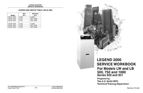
TABLE 3<br />
LEGEND 2000 ORIFICE TABLE<br />
LW/LB-500&750&1000<br />
LEGEND HEATERS<br />
SERVICE WORKBOOK<br />
MAKE-UP AIR<br />
Direct Communication<br />
MODEL<br />
SIZE<br />
(IN.)<br />
ELEVATION<br />
(FT )<br />
LW/LB-500 0.391 0-2000<br />
LW/LB-500 0.384 2001-3000<br />
LW/LB-500 0.374 3001-4000<br />
LW/LB-500 0.229 0-2000<br />
LW/LEl-500 0.226 2001-3000<br />
LW/LB-500 0.223 3001-4000<br />
LW/LB-750(USA) 0.484 0-2000<br />
LW/LB-750(USA) 0.469 2001-3000<br />
LW/LB-750(USA) 0.461 3001-4000<br />
LW/LB-750(CAN) 0.464 0-2000<br />
LW/LB-750(CAN) 0.450 2001-3000<br />
LW/LB-750(CAN) 0.443 3001-4000<br />
LW/LB-750 0.286 0-2000<br />
LW/LB-750 0.282 2001-3000<br />
LW/LB-750 0.278 3001 -4000<br />
LW/LB-1000 0.555 0-2000<br />
LW/LB 1000 0.537 2001-3000<br />
LW/LB 1000 0.533 3001-4000<br />
LW/LB-1000 0.333 0-2000<br />
LW/LB-100 0.329 2001-3000<br />
LW/LB-100 0.325 3001-4000<br />
* Factory installed orifice.<br />
Conventional Venting<br />
(Where room air is used for combustion)<br />
A fresh supply of make-up air for combustion can be supplied to the heater through<br />
make-up air ducts, which directly communicate with the out of doors. Two openings are<br />
required - one within 12 inches of the top of the enclosure and one within 12 inches of<br />
the bottom of the enclosure. Each opening shall have a free area (add for louvers,<br />
screens, etc.) of not less than 1 square inch per 4000 BTUH of the total input of all<br />
appliances within the enclosure.<br />
The lower opening is primarily providing combustion air. The upper opening is<br />
providing combustion air and acts as a relief opening for room heat. Direct vent<br />
installations would draw their combustion air from outdoors through an air intake vent<br />
connected directly to the heater.<br />
A.O. <strong>Smith</strong> <strong>Water</strong> Products Co.<br />
Irving, Texas © 1997<br />
74<br />
Service Workbook<br />
Training Department<br />
A.O. <strong>Smith</strong> <strong>Water</strong> Products Co.<br />
Irving, Texas © 1997<br />
6<br />
Service Workbook<br />
Training Department
LEGEND HEATERS<br />
SERVICE WORKBOOK<br />
MAKE-UP AIR<br />
Vertical Ducts<br />
LEGEND HEATERS<br />
SERVICE WORKBOOK<br />
7. SET THE INTAKE AIR PRESSURE.<br />
Turn off the gas to the burner or boiler so the unit will not fire. Disconnect the tube<br />
going from the blower to the pressure switch and connect your manometer here. Start<br />
the blower and adjust the air shutter so that the manometer reads a minimum of 4.5" to<br />
a maximum of 5.0" of water column. Too much air will cause the unit to backfire and/or<br />
collapse the flue.<br />
8. VERIFY SUPPLY LINE GAS PRESSURE<br />
The ideal supply pressure is a minimum 7" water column. Under no circumstances<br />
should the supply pressure be less than 5.5" wc. If you find low gas pressure, STOP!<br />
You will probably experience hard starting and run the risk of damaging the unit if you<br />
try starting it. Have the problem corrected before continuing.<br />
9. ADJUST MANIFOLD GAS PRESSURE<br />
Turn the gas off and run the unit through a firing cycle. The gas pressure should be no<br />
less than 3.0" and no more than 3.5" water column pressure. The pressure is factory<br />
preset and should only require slight adjustments if any.<br />
10. PERFORM THE START UP PROCEDURE AS LISTED IN THE MANUAL.<br />
You may have to make slight adjustments to blower air and gas pressures to get the<br />
unit on rate and within correct combustion specifications. The unit should now operate<br />
smoothly and quietly.<br />
Often it is more practical to install vertical make-up air ducts to the out of doors. Again,<br />
two openings are required - one terminating within 12 inches of the top of the enclosure<br />
and one terminating within 12 inches of the bottom of the enclosure. Each opening<br />
shall have a free area of not less than 1 square inch per 4000 BTUH of the total input of<br />
all appliances within the enclosure.<br />
Not applicable to direct vent installations.<br />
A.O. <strong>Smith</strong> <strong>Water</strong> Products Co.<br />
Irving, Texas © 1997<br />
7<br />
Service Workbook<br />
Training Department<br />
A.O. <strong>Smith</strong> <strong>Water</strong> Products Co.<br />
Irving, Texas © 1997<br />
73<br />
Service Workbook<br />
Training Department
LEGEND HEATERS<br />
SERVICE WORKBOOK<br />
MODIFIED GAS TRAIN<br />
This allows the combination valve, which has a diaphragm for pressure regulation, to<br />
always "see" inlet supply gas pressure allowing it to respond more rapidly once<br />
energized. This gets the correct flow of gas to the burner faster.<br />
LEGEND HEATERS<br />
SERVICE WORKBOOK<br />
MAKE-UP AIR<br />
Horizontal Ducts<br />
Note: Legend boilers built in the plant after January 1, 1997 will have the gas valves<br />
arranged like this.<br />
4. POSITION THE BURNER HIGHER<br />
The burner is shimmed up 3/8" in this step. This puts the ports closer to the hot surface<br />
ignitor element and allows quicker ignition of the gas & air mixture entering the<br />
combustion chamber. Shims are made by sandwiching standard burner gaskets<br />
together.<br />
Note: Legend boilers built in the plant after January 1, 1997 will have the burners<br />
installed like this.<br />
5. REPLACE THE INTAKE AIR SHUTTER FOR INCREASED ADJUSTMENT<br />
Use a revised air shutter obtained from the parts department. It is included in the<br />
spacer kit.<br />
6. DRILL A PRESSURE RELIEF HOLE(S) IN THE PVC AIR INTAKE.<br />
This step only applies to direct vent models. Drill a 1.5", or two 1" holes in the underside<br />
of the PVC air intake as close to the blower as practical. This hole(s) allows for the split<br />
second back pressure wave created by gas ignition to vent on the low pressure air<br />
intake side rather than pressurizing the combustion chamber and exhaust, disrupting<br />
the flame pattern, and affecting smooth burner light off.<br />
There is no need to provide additional combustion air to the boiler room. A negligible<br />
amount of air is drawn in through the relief hole. The relief holes should be included on<br />
any new direct vent installation.<br />
START UP PROCEDURES<br />
The following steps must be followed accurately to ensure smooth boiler operation. You<br />
will require the equipment listed at the start of this bulletin. If you do not have the<br />
equipment, or are unsure of proceeding, STOP! Get a qualified service technician with<br />
the right equipment and expertise to finish the job. Failure to make these adjustments<br />
properly could damage the boilers or vent system.<br />
When the heater is installed in an exterior room with no roof access for vertical ducts,<br />
horizontal make-up air ducts should be installed. When using horizontal ducts two<br />
openings are required - one within 12 inches of the top of the enclosure and one within<br />
12 inches of the bottom of the enclosure. Each opening shall have a free area of not<br />
less than 1 square inch per 2000 BTUH of the total input of all appliances within the<br />
enclosure.<br />
Not applicable to direct vent installations.<br />
A.O. <strong>Smith</strong> <strong>Water</strong> Products Co.<br />
Irving, Texas © 1997<br />
72<br />
Service Workbook<br />
Training Department<br />
A.O. <strong>Smith</strong> <strong>Water</strong> Products Co.<br />
Irving, Texas © 1997<br />
8<br />
Service Workbook<br />
Training Department
LEGEND HEATERS<br />
SERVICE WORKBOOK<br />
CONTAMINATED AIR<br />
LEGEND HEATERS<br />
SERVICE WORKBOOK<br />
FIELD FIXING HARD STARTS AND LOCKOUTS ON 1 MILLION<br />
BTU INPUT LEGEND BOILERS AND WATER HEATERS<br />
This set of short instructions should help you diagnose and correct installations<br />
involving I million Btu input Legend boilers. The start up and adjustment of this<br />
equipment requires that you have accurate gauges and combustion analyzers. You<br />
must have a manometer or gauge for reading both incoming and manifold gas<br />
pressures and combustion air blower pressures. You must also have a combustion<br />
analyzer and other gas service related equipment such as a digital multimeter. Do not<br />
bother attempting to make the following adjustments if you do not have the equipment.<br />
NOTE: Improper adjustments and settings of the gas and air pressures can cause<br />
delayed ignition severe enough to crack the tub or collapse the vent!<br />
1. VERIFY CORRECT ELECTRICAL SUPPLY AND POLARITY.<br />
Each LW- 1000 or LB-1000 with a pump on the same circuit requires a minimum<br />
breaker size of 30A and supply wiring sized accordingly. For a boiler without a pump on<br />
the same circuit, the rating should be 15A. It is very important that each Legend be on<br />
its own seperate circuit to prevent voltage variations from affecting the ignition. Low<br />
voltage and over current conditions will affect blower speed and ignition system<br />
performance. This in turn causes hard starts or no starts and lockout.<br />
2. VERIFY GAS SUPPLY LINE SIZING.<br />
Verify that the gas lines to the units are sized according to established guidelines listed<br />
in the installation manual or the National Fuel Gas Code handbook. (The tables in the<br />
manual are from this book.) If you find undersized supply lines, STOP! You will probably<br />
experience hard starting and run the risk of damaging the unit if you try to start the unit.<br />
Have the problem corrected before continuing.<br />
Along with adequate make-up air, the quality of the air is important. Contaminants in<br />
combustion air can lead to premature heater failure. Vapors from bleaches, soaps, hair<br />
spray, freon, waxes, salts, etc. are drawn into the combustion chamber with the makeup<br />
air and, once fired, mix with water vapor in the gases to form extremely corrosive by<br />
products. Dust drawn in may build up on the blower or clog main burner ports. Also, be<br />
certain to examine the exterior area around the air intake of a direct vent installation for<br />
these contaminants.<br />
3. MODIFICATION TO THE GAS CONTROL LAYOUT<br />
The combination pressure regulating gas valve and redundant solenoid safety valve<br />
must be reversed. Existing Legends have the controls laid out as follows: gas inlet<br />
union, gas solenoid valve, combination valve and manual firing valve then main burner<br />
orifice. The new arrangement is to have: gas inlet union, combination valve, solenoid<br />
valve, firing valve and then main burner orifice. Your modified gas train should look like<br />
the picture below.<br />
A.O. <strong>Smith</strong> <strong>Water</strong> Products Co.<br />
Irving, Texas © 1997<br />
9<br />
Service Workbook<br />
Training Department<br />
A.O. <strong>Smith</strong> <strong>Water</strong> Products Co.<br />
Irving, Texas © 1997<br />
71<br />
Service Workbook<br />
Training Department
LEGEND HEATERS<br />
SERVICE WORKBOOK<br />
BURNER SPACER INSTRUCTIONS<br />
• TURN OFF POWER AND SHUT OFF GAS TO THE BOILER.<br />
• REMOVE THE BURNER BY DISCONNECTING THE GAS ORIFICE UNION, THE<br />
BLOWER ADAPTER AND REMOVING THE NUT FROM THE SIX STUDS<br />
AROUND THE FLANGE AT THE TOP PLATE.<br />
• PLACE THE SPACER WITH THE RED GASKET FACING UP OVER THE STUDS-<br />
LEAVE THE ORIGINAL GASKET ON THE TOP PLATE AS SHOW IN THE<br />
DIAGRAM.<br />
• PLACE BOTH BURNER INSULATION PADS ON THE BASE OF THE BURNER.<br />
• REPLACE THE BURNER, GASKET AND PREMIX TUBE FLANGE AS SHOWN.<br />
• THE U-BOLTS THAT HOLD THE GAS TRAIN TO THE FRAME MUST BE<br />
LOOSENED TO ALLOW THE 3/8” RUBBER SHIM TO BE PLACED BETWEEN<br />
THE FRAME AND THE GAS TRAIN PIPE.<br />
• REMOVE THE BLOWER<br />
• REMOVE THE BLOWER SUPPORT BRACKET BY REMOVNG THE NUT FROM<br />
THE STUD ATTACHED TO THE TUB FRAME.<br />
• REPLACE WITH THE NEW BLOWER SUPPORT BRACKET INCLUDED IN THE<br />
KIT. A SCREW HOLE WILL NEED TO BE DRILLED INTO THE JACKET FRAME<br />
FOR ADDITIONAL SCREW.<br />
• REMOVE THE BLOWER SHUTTER BY REMOVING THE NUT FROM THE<br />
BLOWER ADAPTER ASSEMBLY.<br />
• REPLACE WITH THE NEW BLOWER SHUTTER INCLUDED IN THE KIT.<br />
• REPLACE ALL PARTS REMOVED ABOVE.<br />
• TURN THE GAS SUPPLY AND POWER "ON" AND RESTART THE BOILER.<br />
LEGEND HEATERS<br />
SERVICE WORKBOOK<br />
FLAMMABLE ITEMS<br />
Flammable items or pressurized containers of any other potentially hazardous articles<br />
must never be placed on or adjacent to the heater. Open containers of flammable<br />
material should not be stored or used in the same room with the heater or in the area of<br />
the exterior air intake of a direct vent installation. Direct venting does not eliminate the<br />
need to remove flammables or corrosives from the area surrounding the heater.<br />
A.O. <strong>Smith</strong> <strong>Water</strong> Products Co.<br />
Irving, Texas © 1997<br />
70<br />
Service Workbook<br />
Training Department<br />
A.O. <strong>Smith</strong> <strong>Water</strong> Products Co.<br />
Irving, Texas © 1997<br />
10<br />
Service Workbook<br />
Training Department
LEGEND HEATERS<br />
SERVICE WORKBOOK<br />
GAS PRESSURE REQUIREMENTS<br />
LEGEND HEATERS<br />
SERVICE WORKBOOK<br />
Product Update: Legend Boilers LB/LW-1000<br />
The field repair kit for Legend 1 MBH has been released. This kit is not only<br />
recommended for units experiencing hard starts, but is also recommended for units<br />
with periodic lock-out problems.<br />
Spacer Kit At Includes:<br />
• Burner Spacer Assembly<br />
• Revised Air Shutter<br />
• Blower Support Bracket<br />
• Gas Line Shim<br />
• Instructions<br />
After Burner Spacer Kit has been installed. The service agent needs to repeat the<br />
start-up procedures.<br />
• Blower pressure should be set between 4.5" and 5" w.c.<br />
• Gas manifold pressure should be set between 3" w.c. and 3.5" w.c.<br />
• CO 2 readings should be:<br />
8.0 to 9.5% for Natural Gas<br />
8.5 to 10.0% for Propane<br />
Ref: Operation information table on page 19.<br />
The supply gas pressure is measured at the tap indicated. This reading must be<br />
measured with ‘flowing’ gas.<br />
The manifold gas pressure is measured at the manifold pressure tap as indicated.<br />
A.O. <strong>Smith</strong> <strong>Water</strong> Products Co.<br />
Irving, Texas © 1997<br />
11<br />
Service Workbook<br />
Training Department<br />
A.O. <strong>Smith</strong> <strong>Water</strong> Products Co.<br />
Irving, Texas © 1997<br />
69<br />
Service Workbook<br />
Training Department
IRI Equipped Model – Cont.<br />
LEGEND HEATERS<br />
SERVICE WORKBOOK<br />
B. If the flame is not sensed during the TFI period, the system will go into lockout<br />
sounding an alarm (blower and pump will shutdown). A manual reset of power to<br />
the unit is required in order to restart the boiler.<br />
LEGEND HEATERS<br />
SERVICE WORKBOOK<br />
GAS PRESSURE REQUIREMENTS<br />
11. Should any switch open, the "J2-6" contacts will de-energize. Subsequently the<br />
"J1-3" contacts are de-energized closing the gas valve and extinguishing the flame.<br />
The post purge cycle begins and the Pump and Blower remain on for approximately<br />
45 seconds until the post purge cycle ends.<br />
A. If the flame was extinguished due to the System Controller or Operating Control<br />
becoming satisfied, the boiler goes into "standby" awaiting the next "call for<br />
heat".<br />
B. If the flame was extinguished for any other reason, the boiler will go into lockout<br />
and sound an alarm. A manual reset of the power to the boiler will be required in<br />
order to initiate a new ignition sequence.<br />
C. If the flame was extinguished due to the High Limit contacts opening, depressing<br />
the manual reset button as well as resetting of the power to the boiler is required<br />
in order to initiate a new ignition sequence.<br />
The supply gas pressure is measured at the tap indicated. This reading must be<br />
measured with ‘flowing’ gas.<br />
The manifold gas pressure is measured at the manifold pressure tap as indicated.<br />
A.O. <strong>Smith</strong> <strong>Water</strong> Products Co.<br />
Irving, Texas © 1997<br />
68<br />
Service Workbook<br />
Training Department<br />
A.O. <strong>Smith</strong> <strong>Water</strong> Products Co.<br />
Irving, Texas © 1997<br />
12<br />
Service Workbook<br />
Training Department
LEGEND HEATERS<br />
SERVICE WORKBOOK<br />
GAS PRESSURE REQUIREMENTS<br />
IRI Equipped Models – Cont.<br />
LEGEND HEATERS<br />
SERVICE WORKBOOK<br />
1. The System Controller (i.e. tank temperature control, room thermostat, etc.) closes<br />
"calling for heat." If the water temperature is below the OPERATING CONTROL<br />
setting, its contacts remain closed.<br />
Note: In absence of a System Controller, the Operating Control will act as a substitute<br />
(on constant pumping applications only).<br />
2. This powers the "J2-9" contacts on the Ignition Module which in turn powers the<br />
"J1-1" contacts. The coil (1 R) in the 120 VAC DPST relay is now energized which<br />
closes its contacts to the Circulating Pump and the Blower. Both Blower and<br />
Circulating Pump come on [pre-purge cycle begins].<br />
3. With the Blower and Pump operational, the Air Flow Switch and <strong>Water</strong> Flow Switch<br />
contacts close. The Low <strong>Water</strong> Cutoff contacts are closed if the boiler is full of<br />
water.<br />
4. If the circulating water temperature is below the High Limit Control setting, its<br />
contacts remain closed.<br />
5. When the gas supply pressure rises above the Low Gas Pressure Switch setting,<br />
the contacts close. The High Gas Pressure Switch contacts are normally closed. If<br />
the gas valve outlet pressure rises above the set point, the switch contacts will open.<br />
6. The Blocked Flue Switch contacts are normally closed. If the exhaust pipe vent is<br />
blocked, the switch contacts will open.<br />
7. With all switches closed, the "J2-6" contacts on the ignition module is powered.<br />
8. Once the pre-purge cycle ends ,the Ignitor is energized and the proving period<br />
begins (the Ignitor should begin to glow).<br />
The supply gas pressure is measured at the tap indicated. This reading must be<br />
measured with ‘flowing’ gas.<br />
The manifold gas pressure is measured at the manifold pressure tap as indicated.<br />
9. After the Ignitor current reaches a preset amperage, the "J1-3" contacts and the<br />
flame rectification circuit in ignition module are energized. The Gas Valves are now<br />
powered. The position indicator switches on the gas valves change states and the<br />
"J2-7" contacts are energized. The proving period ends and Trial For Ignition (TFI)<br />
begins.<br />
10. The Ignitor ignites the incoming gas mixture. Upon proof of flame, the ignitor is<br />
shut-off and it will now act as a flame sensor, monitoring the continued presence of<br />
flame.<br />
A. If the flame is sensed by the Ignitor, power to the Ignitor is disconnected, the<br />
glow diminishes and the flame remains on.<br />
A.O. <strong>Smith</strong> <strong>Water</strong> Products Co.<br />
Irving, Texas © 1997<br />
13<br />
Service Workbook<br />
Training Department<br />
A.O. <strong>Smith</strong> <strong>Water</strong> Products Co.<br />
Irving, Texas © 1997<br />
67<br />
Service Workbook<br />
Training Department
LEGEND HEATERS<br />
SERVICE WORKBOOK<br />
14. The High Limit may be checked by, noting all temperature settings, changing the<br />
settings, changing the system controller and operating control to a higher set point<br />
than the limit itself and running the boiler. Allow the boiler to shut down on High<br />
Limit. This can be accomplished quicker by having the High Limit set just above the<br />
actual outlet temperature indicated on the LED. After shut down, the boiler should<br />
not fire up until the manual reset button is depressed and power to the unit is reset.<br />
The operating control and the system controller may be tested in a similar fashion<br />
but a shut down on either will not require the power to the boiler to be reset. Return<br />
all temperature settings to the original positions upon completion of tests.<br />
LEGEND HEATERS<br />
SERVICE WORKBOOK<br />
AIR PRESSURE CHECK WITH DRAFT GAUGE<br />
15. Safety valves may be checked for proper closure upon loss of flame. The valves<br />
should positively stop the flow of gas to the burner within 5 seconds of being deenergized.<br />
The voltage to the valve terminals may be checked for loss of power<br />
when a flame failure occurs by closing the manual test firing valve just ahead of the<br />
gas orifice location. Plugged leak test valves have been provided on the<br />
downstream side of both safety shut-off valves. The leak test valve for the second<br />
safety shut-off valve is located in the gas piping between the safety shut-off valve<br />
and the manual shut-off valve. The plug may be removed to allow a pressure gauge<br />
to be inserted to verify proper closure of the valves. The first safety shut-off valve<br />
may be checked by energizing the vent valve solenoid to close it and closing the<br />
manual shut-off valve. The safety shut-off valve should close and the pressure<br />
should stabilize. The second safety shut-off valve may be checked while the manual<br />
shut-off valve is closed. De-energize the vent valve second safety shut-off valve and<br />
the manual shut-off and verify that the pressure is stabilized between the valve. The<br />
pressure should not drop to ensure positive closure. In either case, if a steady<br />
increase in pressure is indicated, the valve under test should be replaced.<br />
16. The dirt leg and gas strainer (if required) should be inspected periodically for<br />
accumulation of foreign debris that could cause blockage. Gas should be shut off<br />
ahead of the particular device to be cleaned or inspected to prevent gas leakage.<br />
OPERATING SEQUENCE<br />
The IRI version of the RAM Ignition Module provides for a single ignition trial or a single<br />
flame failure condition before a lockout occurs. An alarm is sounded in the event of a<br />
lockout condition. A lockout requires that the power to the boiler be manually reset.<br />
Once the ON/OFF switch closes, the "POWER" on the DIA-SCAN lights up and<br />
uninterrupted power is applied to:<br />
A) 120/24 VAC Transformer (LINE)<br />
B) "J1-2" on RAM Ignition Module (LINE)<br />
C) "J2-8" on RAM Ignition Module (24 VAC)<br />
Only the LW/LB-1000 has an adjustable air shutter. Typically, the service agent will<br />
adjust this air shutter for a 4.5-5.0” positive w.c. air pressure reading at the blower outlet<br />
for smoothest ignition. Note: (The models 500 and 750 have a blower rheostat to allow<br />
adjustment for smooth ignition.)<br />
A.O. <strong>Smith</strong> <strong>Water</strong> Products Co.<br />
Irving, Texas © 1997<br />
66<br />
Service Workbook<br />
Training Department<br />
A.O. <strong>Smith</strong> <strong>Water</strong> Products Co.<br />
Irving, Texas © 1997<br />
14<br />
Service Workbook<br />
Training Department
LEGEND HEATERS<br />
SERVICE WORKBOOK<br />
VENTING OPTIONS<br />
Outside air intake and exhaust terminations should be located so exhausted flue gas<br />
moisture will not condense and freeze over the air intake or cause a nuisance or hazard<br />
to pedestrians or the equipment. (Ref: NFPA 54, ANSI Z223. 1, for complete Guidelines).<br />
LEGEND HEATERS<br />
SERVICE WORKBOOK<br />
TABLE 1 PERIODIC TESTING RECOMMENDATIONS FOR IRI<br />
EQUIPPED MODELS<br />
Item Frequency Accomplished By Remarks<br />
1. Gages and Indicators Daily Operator Visually inspect, log<br />
observations<br />
2. Burner Flame Daily Operator Visually inspect for<br />
uniform blue flames<br />
3. Flame Signal Strength Weekly Operator Check flame signal<br />
strength with meter<br />
and log<br />
4. Flame Failure Detection Weekly Operator Close Manual<br />
Shutoff Valve,<br />
check safety<br />
shutdown time, log<br />
5. Gas Valves Weekly Operator Open Operating<br />
Control, listen for<br />
valve closure,<br />
check for voltage<br />
6. Flow Switch/ Low <strong>Water</strong><br />
cutoff<br />
Weekly Operator See detailed<br />
instructions<br />
7. Vent System Monthly Operator See Operating<br />
Manual<br />
8. Condensate Drains Monthly Operator See Operating<br />
Manual<br />
9. Blocked flue and blower Monthly Operator See detailed<br />
instructions<br />
10. Gas pressure switches Monthly Operator See detailed<br />
instructions<br />
11. Burner components Semiannually Service Technician See detailed<br />
instructions<br />
12. Transformer Semiannually Service Technician Check primary &<br />
secondary voltage,<br />
log<br />
13. High Limit and<br />
Operating Control<br />
Annually Service Technician See detailed<br />
instructions<br />
14. Safety Valves As Required Operator See detailed<br />
15. Drip Leg and gas<br />
strainer<br />
instructions<br />
As Required Operator See detailed<br />
instructions<br />
Direct Venting: Maximum 60 equivalent feet exhaust and 60 equivalent feet intake air<br />
vent.<br />
IRI Equipped Models – Cont.<br />
A.O. <strong>Smith</strong> <strong>Water</strong> Products Co.<br />
Irving, Texas © 1997<br />
15<br />
Service Workbook<br />
Training Department<br />
A.O. <strong>Smith</strong> <strong>Water</strong> Products Co.<br />
Irving, Texas © 1997<br />
65<br />
Service Workbook<br />
Training Department
LEGEND HEATERS<br />
SERVICE WORKBOOK<br />
4. or in the range of 40 - 400 Ohms for the LW/LB-500&750 ignitor.<br />
5. If a flame failure is detected the boiler should shut off within one second. This may<br />
be accomplished by closing the manual shutoff valve just ahead of the gas orifice,<br />
checking for gas valve closure and timing by watching the Dia-Scan indicator or<br />
checking voltage at the gas valve.<br />
6. Open the operating control contacts by momentarily turning the dial down until<br />
"satisfied". Listen for valve closure and verify no voltage to either valve. Return<br />
operating control to its normal setting.<br />
7. The flow switch may be tested by verifying switch position when water is flowing<br />
through the system and when flow ceases. With water flowing through the system,<br />
the circuit between the red and yellow terminals on the switch will be closed. When<br />
water flow drops or ceases in the system, the circuit between the red and yellow<br />
terminals will be open. These two conditions may be verified with a continuity meter.<br />
The low water cutoff can be tested by checking for continuity between terminals 3 &<br />
4. With no water present there should be no continuity.<br />
8. The vent system shall be maintained per the Venting Maintenance section in the<br />
operation manual.<br />
9. The condensate lines shall be maintained per the Condensate Removal System<br />
section in the operation manual.<br />
10. The blocked flue switch contacts may be opened by applying a positive pressure<br />
greater than 1 " w.c. to the barbed fitting. The boiler will shut down if running or not<br />
start up. The blower prover switch may be checked by disconnecting the tube at its<br />
barbed fitting. The boiler will shut down if running or not start up. A manual reset of<br />
power to the boiler is required to start up again.<br />
LEGEND HEATERS<br />
SERVICE WORKBOOK<br />
CONVENTIONAL VENTING<br />
11. The low gas pressure switch contacts may be opened by closing the manual shutoff<br />
valve in the gas supply to the boiler. The boiler will shut down if running or not start<br />
up. The high gas pressure switch requires an increase in gas pressure in order for<br />
its contacts to be opened. The boiler will shut down if running or won't start if gas<br />
pressure in excess of 1 1/2 times its normal manifold pressure is applied at its<br />
connecting port. A shut down on any of the switches in the safety circuit will require<br />
a reset of the power to the boiler.<br />
12. The burner should be maintained per the Burner Maintenance Section of the<br />
operation manual.<br />
13. The transformer voltages can be checked with a voltmeter and the values recorded.<br />
Conventional Venting - May be horizontal or vertical. Maximum of 60 equivalent feet<br />
of exhaust vent. (Uses room air for intake.)<br />
A.O. <strong>Smith</strong> <strong>Water</strong> Products Co.<br />
Irving, Texas © 1997<br />
64<br />
Service Workbook<br />
Training Department<br />
A.O. <strong>Smith</strong> <strong>Water</strong> Products Co.<br />
Irving, Texas © 1997<br />
16<br />
Service Workbook<br />
Training Department
LEGEND HEATERS<br />
SERVICE WORKBOOK<br />
LADDER DIAGRAM<br />
LEGEND 2000<br />
System Thermostat Calls for Heat<br />
Heat<br />
IRI Equipped Models – Cont.<br />
LEGEND HEATERS<br />
SERVICE WORKBOOK<br />
inspection and maintenance may be necessary.<br />
Precautions shall be taken to protect against bodily injury or property damage while<br />
tests are being conducted. Cover plates that require removal in order to gain access to<br />
items requiring maintenance or testing shall be replaced before the boiler is put back<br />
into service.<br />
Pump Starts<br />
Flow Switch Closes<br />
Fan Prepurge<br />
Air Prover Switch Closes<br />
Operators or maintenance technicians should follow the recommended procedures set<br />
forth in the instructions and allow for any additional circumstances that arise based on<br />
the particular installation when preparing a maintenance program.<br />
HSI Energizes<br />
SEQUENCE OF OPERATION<br />
Open Gas Valve<br />
Burner Ignition<br />
HSI Verifies Flame<br />
Fan Speed Returns to Normal<br />
System Thermostat Satisfies<br />
Gas Valve Closes<br />
45 Sec. Blower and Circulator Post Purge<br />
Fan Speed Reduced<br />
Blows<br />
To understand Legend water heaters, an examination of their sequence of operation is<br />
necessary.<br />
The operator or technician should thoroughly understand the operating procedures and<br />
recognize an equipment malfunction. Any defects found should be corrected<br />
immediately.<br />
The table provided herein is a recommended guideline to follow for periodic testing of<br />
the boilers safety devices and controls. Detailed maintenance procedures are included.<br />
The results of the periodic testing should be recorded in a suitable log book at the time<br />
of testing.<br />
TESTING AND MAINTENANCE INSTRUCTIONS<br />
1. Dia Scan indicators should be visually inspected on a daily basis for normal<br />
operation of the boiler. The temperature indicators should be inspected and the<br />
differential temperatures recorded while the boiler is firing. If the temperature<br />
differential increases by five degrees from the time the boiler was first put into<br />
service, a general deliming of the heat exchanger may be in order. The initial<br />
temperature differential should be established per the procedures in the operation<br />
manual.<br />
2. Visually inspect the flame through the observation port for a uniform hard blue<br />
flame.<br />
3. The flame signal strength may be checked by placing a digital multimeter in series<br />
with the sensor lead. The red lead should be unplugged from the ignitor and the<br />
meter inserted in series. Once the boiler has established a flame, a signal of at least<br />
one microamp should be indicated. If a weaker signal is present, then the flame may<br />
not be impinging on the ignitor properly or the ignitor may be at fault. To check for a<br />
faulty ignitor the cold resistance is measured by shutting the boiler down and<br />
allowing the ignitor to cool to room temperature. The ignitor leads are then<br />
disconnected and an Ohm meter is hooked up across the leads. The resistance<br />
value should be in the range of 45 - 75 Ohms for the LW/LB-1000 Ignitor<br />
IRI Equipped Models – Cont.<br />
A.O. <strong>Smith</strong> <strong>Water</strong> Products Co.<br />
Irving, Texas © 1997<br />
18<br />
Service Workbook<br />
Training Department<br />
A.O. <strong>Smith</strong> <strong>Water</strong> Products Co.<br />
Irving, Texas © 1997<br />
63<br />
Service Workbook<br />
Training Department
LEGEND HEATERS<br />
SERVICE WORKBOOK<br />
LEGEND 2000 IRI SCHEMATIC DIAGRAM<br />
LEGEND HEATERS<br />
SERVICE WORKBOOK<br />
TOUBLESHOOTING LEGEND WATER HEATERS<br />
To troubleshoot a Legend water heater check that:<br />
RAM HSI Control<br />
• 120 VAC is supplied to the heater<br />
• the system is full of water<br />
10<br />
9 8 7 6 5 4 3 2 1<br />
• gas is supplied to the unit<br />
• the heater is properly grounded<br />
• vent installation is proper<br />
• combustion air is provided<br />
X<br />
1. Inducer<br />
2. Ignitor - 1<br />
3. 120V - Hot<br />
4. 120V - RTN<br />
5. Ignitor - 2<br />
6. Ground<br />
7. Valve<br />
8. Pressure SW<br />
9. Thermostat<br />
10. 24 Vac Hot<br />
X<br />
• condensate drain tubes are operational<br />
• on/off switch is “on”<br />
LEGEND OPERATING INFORMATION TABLE<br />
Model Description Model 500 Model 750 Model 1000<br />
Air Blower<br />
Blocked Flue Switch<br />
Blower Prover Switch<br />
Low Gas Pressure Switch<br />
Restricted Gas Pressure Switch<br />
Manifold Gas Pressure<br />
<strong>Water</strong> Flow Switch<br />
4.5-5.0” w.c. Positive Exhaust Pressure<br />
1.0” w.c. Positive to Close<br />
1.0” w.c. Positive to Close<br />
5.5" w.c. Supply press to close (Min 7.0" w.c.<br />
recommended) - Natural Gas<br />
10.5" w.c. Supply press to close (11.5" w.c.<br />
recommended) - Propane Gas<br />
.15” w.c. Positive to Close<br />
Approximately 3.5” w.c. – Natural Gas<br />
Approximately 10.0” w.c. – Propane Gas<br />
25 GPH Flow Closes<br />
Hot Surface Ignitor (HSI) Surface Cold – 75-400 OHMS Cold – 40-75 OHMS<br />
A.O. <strong>Smith</strong> <strong>Water</strong> Products Co.<br />
Irving, Texas © 1997<br />
62<br />
Service Workbook<br />
Training Department<br />
A.O. <strong>Smith</strong> <strong>Water</strong> Products Co.<br />
Irving, Texas © 1997<br />
19<br />
Service Workbook<br />
Training Department
LEGEND HEATERS<br />
SERVICE WORKBOOK<br />
SUPPLY VOLTAGE POLARITY CHECK<br />
LEGEND HEATERS<br />
SERVICE WORKBOOK<br />
LEGEND 2000 IRI CONNECTION DIAGRAM<br />
S<br />
T<br />
E<br />
P<br />
Supply voltage Polarity Check<br />
1 Using a multimeter, check supply black to ground, white to ground and<br />
green to ground voltage (in the junction box on the back of the<br />
Legend).<br />
RESULTS<br />
If the meter:<br />
does not read 120 VAC<br />
does read 120 VAC<br />
does not read “0” white to ground<br />
does read “0” white to ground<br />
then<br />
check supply voltage<br />
go to Step 2.<br />
check supply wiring<br />
go to Step 2.<br />
A.O. <strong>Smith</strong> <strong>Water</strong> Products Co.<br />
Irving, Texas © 1997<br />
20<br />
Service Workbook<br />
Training Department<br />
A.O. <strong>Smith</strong> <strong>Water</strong> Products Co.<br />
Irving, Texas © 1997<br />
61<br />
Service Workbook<br />
Training Department
LEGEND HEATERS<br />
SERVICE WORKBOOK<br />
LEGEND HEATERS<br />
SERVICE WORKBOOK<br />
HSI CONTROL SUPPLY VOLTAGE TEST<br />
Hot Surface Ignition Control<br />
S<br />
T<br />
E<br />
P<br />
HSI Control Supply Voltage Test<br />
2 Test for 120 VAC between HSI terminal 3 and ground (terminal 6).<br />
RESULTS<br />
If the meter:<br />
then<br />
does not read 120 VAC • check wiring to On/Off<br />
switch.<br />
• check internal 10 amp fuse.<br />
does read 120 VAC go to step 3.<br />
A.O. <strong>Smith</strong> <strong>Water</strong> Products Co.<br />
Irving, Texas © 1997<br />
60<br />
Service Workbook<br />
Training Department<br />
A.O. <strong>Smith</strong> <strong>Water</strong> Products Co.<br />
Irving, Texas © 1997<br />
21<br />
Service Workbook<br />
Training Department
LEGEND HEATERS<br />
SERVICE WORKBOOK<br />
TRANSFORMER TEST – SECONDARY VOLTAGE<br />
LEGEND HEATERS<br />
SERVICE WORKBOOK<br />
single trial version with an alarm contact. Any failure that is sensed by a component in<br />
the safety circuit or the gas valve position indicating switches will cause the boiler to<br />
simultaneously shut down the gas valves while opening the vent valve, purge the<br />
combustion chamber, continuously sound the alarm and lock out. The power to the<br />
ignition module must be manually reset to restart the boiler.<br />
INSTALLATION<br />
The gas control train has a main manual gas shutoff valve installed at the factory. A gas<br />
service pressure regulator is required to maintain a gas supply pressure below the<br />
maximum allowable pressure indicated on the appliance rating plate. A dirt leg shall be<br />
provided in the gas piping per the National Fuel Gas Code (NFPA 54).<br />
S<br />
T<br />
E<br />
P<br />
RESULTS<br />
Transformer Test – Secondary Voltage<br />
3<br />
Test for 24 VAC between the two transformer terminals.<br />
If the meter:<br />
then<br />
does not read 24 VAC<br />
• check 120 VAC supply<br />
connection to primary side<br />
of transformer. (Step 1)<br />
• replace transformer.<br />
does read 24 VAC go to step 4.<br />
Vent lines from gas regulators, switches, and any other equipment requiring<br />
atmospheric pressure to balance a control diaphragm can be manifolded together. The<br />
manifolded line should have a diameter not less than the largest vent line plus 50 % of<br />
the area of the additional vent lines. For example, if the largest vent line is 1/4 inch and<br />
the vent line from the safety switch is 1/8 inch, the manifolded line should be 5/16 inch<br />
minimum. These vent lines should not be manifolded to the following: Vent lines<br />
between the two safety shut-off valves.<br />
Vent lines from the pressure relief valve if provided.<br />
Vent lines from the ignition or main burner systems.<br />
Vent lines from other boilers.<br />
Vent lines between the two safety shut-off valves on the individual burner lines and the<br />
vent lines from the pressure relief valve, if provided, can be manifolded together. The<br />
diameter of the manifolded line must not be less than the largest vent line plus 50% of<br />
the area of the additional vent lines. These vent lines should not be manifolded to the<br />
following:<br />
Vent lines from ignition or main burner systems.<br />
Vent lines from other boilers.<br />
A permanent means for making periodic tightness tests of the safety shut-off valves is<br />
provided for with the appropriate leak test valves located on the downstream side of<br />
each safety shut-off valve.<br />
The boiler shall not be released for operation before the installation, checkout and<br />
start-up has been performed according to the installation, operation and maintenance<br />
manual, the LEGEND 2000 start- up procedures and this insert sheet.<br />
TESTING AND MAINTENANCE<br />
The effective operation of all safety and control devices depends upon their ability to<br />
respond to their activating impulses, therefore it is important that they remain in proper<br />
operating condition at all times. An inspection and maintenance schedule should be<br />
established and performed on a periodic basis. During initial operation, more frequent<br />
A.O. <strong>Smith</strong> <strong>Water</strong> Products Co.<br />
Irving, Texas © 1997<br />
22<br />
Service Workbook<br />
Training Department<br />
A.O. <strong>Smith</strong> <strong>Water</strong> Products Co.<br />
Irving, Texas © 1997<br />
59<br />
Service Workbook<br />
Training Department
LEGEND HEATERS<br />
SERVICE WORKBOOK<br />
A.O. SMITH COMMERCIAL COPPER HYDRONIC BOILERS<br />
LEGEND 2000 SERIES I. R. I. MODELS<br />
LEGEND HEATERS<br />
SERVICE WORKBOOK<br />
HSI CONTROL TEST (TERMINAL 10)<br />
GENERAL<br />
The LEGEND 2000 series of boilers, when constructed, installed, operated and<br />
maintained in accordance with the provisions set forth in this Insert along with the<br />
standard Instruction Manuals, is said to be in compliance with the Industrial Risk<br />
Insurers (IRI) position for a water tube boiler. The boiler is built in accordance with the<br />
ASME boiler and pressure vessel code and the IRI IM.4.1.1 information which<br />
references and modifies sections of the ANSI/NFPA 8501 Standard for single burner<br />
boilers and furnaces. This insert sheet is intended to supplement the Instruction<br />
Manuals set supplied with the boiler.<br />
The importance of a well-maintained boiler installation is recognized by insurance<br />
companies. Where a plant does not have a sufficient staff trained in the complete<br />
maintenance of its boiler, a maintenance contract should be established with the boiler<br />
company or an organization which is knowledgeable regarding the boiler and all<br />
subsystems associated with it. Operation, maintenance and inspection should be in<br />
accordance with the National Boiler Inspection Code unless otherwise superseded by<br />
local codes.<br />
Figure 1 shows a typical IRI gas control train for Legend 2000 models. The major<br />
components are identified with a description and part number. Note that the gas trains<br />
are similar with the exception of the gas pressure regulator, the high gas pressure<br />
switch, the ball valve and the piping layout as shown in the figure. The gas control train<br />
uses two solenoid operated gas valves with position indicating switches and a separate<br />
gas pressure regulator to control the flow of gas to the main burner. The gas manifold<br />
pressure is taken at the restricted gas flow switch location. The position indicating<br />
switches are monitored by the ignition module. A third solenoid valve located between<br />
the two larger valves is called a bleed or vent valve. The vent valve relieves any<br />
leakage through the seat of the first safety valve and prevents the development of<br />
pressure upon the seat of the second safety valve. This provides for additional security<br />
against fuel leakage into the combustion chamber when the burner is off. The vent<br />
valve is normally open and must be vented to the atmosphere according to the<br />
INSTALLATION instructions.<br />
Figure 2 and 3 are the connection diagram and the schematic respectively. These<br />
models have additional safety features in the circuit as compared to standard models.<br />
The primary differences are the addition of the high gas pressure switch and the low<br />
water cutoff to the circuit. The Dia-Scan module does not indicate the high gas pressure<br />
switch or the low water cutoff, however the ignition module will energize an alarm bell in<br />
the event of a failure. The boilers operating sequence is controlled by the ignition<br />
module. The operating sequence, included, is similar to that of a standard LEGEND<br />
2000 boiler but does not reduce blower speed at start up. The module is a<br />
S<br />
T<br />
E<br />
P<br />
RESULTS<br />
HSI Control Test (Terminal 10)<br />
4 Test for 24 VAC between the Ram HSI control terminal 10 and ground<br />
(terminal 6).<br />
If the meter:<br />
then<br />
does not read 24 VAC • check wiring to transformer.<br />
• check internal 2 Amp fuse.<br />
does read 24 VAC go to step 5.<br />
A.O. <strong>Smith</strong> <strong>Water</strong> Products Co.<br />
Irving, Texas © 1997<br />
58<br />
Service Workbook<br />
Training Department<br />
A.O. <strong>Smith</strong> <strong>Water</strong> Products Co.<br />
Irving, Texas © 1997<br />
23<br />
Service Workbook<br />
Training Department
LEGEND HEATERS<br />
SERVICE WORKBOOK<br />
SYSTEM (TANK TEMPERATURE) CONTROL TEST<br />
LEGEND HEATERS<br />
SERVICE WORKBOOK<br />
CONNECTION WIRING DIAGRAM FOR LW/LB-1000<br />
S<br />
T<br />
E<br />
P<br />
System (Tank Temperature) Control Test<br />
5 • Adjust control to call for heat.<br />
• Test for 24 VAC between each terminal of the system control and<br />
ground.<br />
RESULTS<br />
If the meter:<br />
then<br />
does not read 24 VAC to either terminal<br />
check wiring from the<br />
transformer.<br />
does not read 24 VAC on both terminals to ground replace control.<br />
reads 24 VAC on both terminals go to Step 6.<br />
A.O. <strong>Smith</strong> <strong>Water</strong> Products Co.<br />
Irving, Texas © 1997<br />
24<br />
Service Workbook<br />
Training Department<br />
A.O. <strong>Smith</strong> <strong>Water</strong> Products Co.<br />
Irving, Texas © 1997<br />
57<br />
Service Workbook<br />
Training Department
LEGEND HEATERS<br />
SERVICE WORKBOOK<br />
CONNECTION WIRING DIAGRAM FOR LW/LB 500 AND 750<br />
LEGEND HEATERS<br />
SERVICE WORKBOOK<br />
OPERATING CONTROL TEST<br />
S<br />
T<br />
E<br />
P<br />
Operating Control Test (This is the automatic reset high<br />
limit on domestic water applications.)<br />
6 Test for 24 VAC between each terminal of the operating control and<br />
ground.<br />
RESULTS<br />
If the meter:<br />
then<br />
does not read 24 VAC from either terminal to ground check wiring to system control.<br />
does read 24 VAC to only one terminal and ground • first check temperature<br />
setting on control – (set at<br />
least 30° higher than system<br />
control (tank temperature<br />
control) setting and retest.<br />
• if still no voltage, replace the<br />
control.<br />
does read 24 VAC from each terminal to ground go to 7.<br />
A.O. <strong>Smith</strong> <strong>Water</strong> Products Co.<br />
Irving, Texas © 1997<br />
56<br />
Service Workbook<br />
Training Department<br />
A.O. <strong>Smith</strong> <strong>Water</strong> Products Co.<br />
Irving, Texas © 1997<br />
25<br />
Service Workbook<br />
Training Department
LEGEND HEATERS<br />
SERVICE WORKBOOK<br />
HSI CONTROL TERMINAL 9 TEST<br />
LEGEND HEATERS<br />
SERVICE WORKBOOK<br />
TABLE FOR STEP 29<br />
S<br />
T<br />
E<br />
P<br />
HSI Control Terminal 9 Test<br />
7 Test for 24 VAC between Ram HSI control terminal 9 and ground<br />
(terminal 6).<br />
Gas Valve Coil – OHMS Resistance Table<br />
LEGEND<br />
MODEL<br />
GAS<br />
TYPE<br />
#1 GAS VALVE<br />
MODEL<br />
LW/B-500<br />
LW/B-750<br />
NG<br />
and<br />
LPG<br />
Robertshaw 7000-<br />
DERHC-STA<br />
#1 GAS<br />
VALVE<br />
COIL OHMS*<br />
#2 GAS VALVE<br />
MODEL<br />
#2 G.V.<br />
COIL<br />
OHMS<br />
69 (TH-TR) __ 14 (Safety<br />
Gas Value)<br />
NG WR-2509-258 64 HNWL-V8843N1006 64<br />
LPG HNWL-V88A1626 64 HNWL-V88A1626 64<br />
LW/B-1000 NG ITT-K3AF671S 5000 HNWL-V8843N1022 64<br />
LW/B-1000 LPG HNWL-V88A1626 64 HNWL-V88A1626 64<br />
*Volts divided by AMPS = OHMS Resistance<br />
Legend Gas Valve Table<br />
Legend Model Type Gas Type Valve<br />
500 for USA and<br />
Canada<br />
750 USA<br />
USA & Canada<br />
Canada<br />
1000 USA and<br />
Canada<br />
Nat/Propane<br />
Natural<br />
Propane<br />
Natural<br />
Natural<br />
Propane<br />
LW Circulator Information<br />
Heater Model<br />
Dual Solenoid<br />
Diaphragm<br />
Solenoid<br />
Diaphragm<br />
Diaphragm<br />
Solenoid<br />
Diaphragm<br />
Solenoid<br />
MISCELLANEOUS INFORMATION ON LEGEND 2000<br />
<strong>Water</strong> GPM @<br />
20°TR<br />
Pressure Drop thru<br />
Heater<br />
Circulator<br />
HP<br />
Circulator<br />
Motor<br />
LW-500 44 12.5 ft. hd. 1 B&G 3531<br />
LW-750 66 17.76 ft. hd. 1 B&G 3531<br />
LW-1000 88 8.8 ft. hd. 1 TACO 1935<br />
AMP DRAW TABLE<br />
RESULTS<br />
If the meter:<br />
then<br />
does not read 24 VAC<br />
check wiring to operating<br />
control.<br />
does read 24 VAC go to Step 8.<br />
Heater Model Blower Amp Pump Amp Ignition System<br />
LW-500 120V; 3.5A 120V; 10.4FLA 120V; 5A Max<br />
LW-750 120V; 3.5A 120V; 14.0FLA 120V; 5A Max<br />
LW-1000 120V; 3.5A 120V; 15.4FLA 120V; 5A Max<br />
A.O. <strong>Smith</strong> <strong>Water</strong> Products Co.<br />
Irving, Texas © 1997<br />
26<br />
Service Workbook<br />
Training Department<br />
A.O. <strong>Smith</strong> <strong>Water</strong> Products Co.<br />
Irving, Texas © 1997<br />
55<br />
Service Workbook<br />
Training Department
LEGEND HEATERS<br />
SERVICE WORKBOOK<br />
GAS VALVE COIL(S) - CONTINUITY CHECK<br />
LEGEND HEATERS<br />
SERVICE WORKBOOK<br />
HSI CONTROL TERMINAL 1 TEST<br />
• Power supply on/off switch is off<br />
• Disconnect white (neutral) leads from gas valve(s)<br />
• Multimeter set to 200 scale and batteries good<br />
S<br />
T<br />
E<br />
P<br />
RESULTS<br />
Gas Valve Coil(s) – Continuity Check<br />
29 Test for coil resistance (OHMS) through each gas valve coil. See<br />
table (page 55) for proper reading.<br />
If the meter:<br />
reads “1” or “0”<br />
reads more than -+7.5% of value listed in table (next<br />
page)<br />
does read within -+7.5% of value listed in table (next<br />
page)<br />
then<br />
replace the gas valve.<br />
replace the gas valve.<br />
gas valves should open and<br />
burner ignite.<br />
S<br />
T<br />
E<br />
P<br />
RESULTS<br />
HSI Control Terminal 1 Test<br />
8 Test for 120 VAC between Ram HSI control terminal 1 and ground<br />
(terminal 6).<br />
If the meter:<br />
then<br />
does not read 120 VAC<br />
replace Ram HSI Control.<br />
does read 120 VAC go to Step 9.<br />
A.O. <strong>Smith</strong> <strong>Water</strong> Products Co.<br />
Irving, Texas © 1997<br />
54<br />
Service Workbook<br />
Training Department<br />
A.O. <strong>Smith</strong> <strong>Water</strong> Products Co.<br />
Irving, Texas © 1997<br />
27<br />
Service Workbook<br />
Training Department
LEGEND HEATERS<br />
SERVICE WORKBOOK<br />
TEST OF 1R (DPST) RELAY – POWER SUPPLY<br />
LEGEND HEATERS<br />
SERVICE WORKBOOK<br />
GAS VALVE(S) 24 VAC CHECK<br />
During 4 Second Trial for Ignition. Ref: Pages 57 and 58 Wiring Diagram<br />
Gas Valve(s) 24 VAC Check.<br />
S<br />
T<br />
E<br />
P<br />
28 Test For 24 VAC between ground and gas valve BL/Y connection and<br />
then ground and gas valve BL/R connection.<br />
S<br />
T<br />
E<br />
P<br />
RESULTS<br />
Test of 1R (DPST) Relay - Power Supply<br />
9 Test for 120 VAC between terminals 0 and 1 on DPST Relay.<br />
If the meter:<br />
then<br />
does not read 120 VAC<br />
check wiring to Ram HSI<br />
control terminal 1 and relay<br />
terminal 1.<br />
does read 120 VAC go to Step 10.<br />
RESULTS<br />
If the meter:<br />
does not read 24 VAC between the gas valve BL/Y<br />
wire connection and ground<br />
does not read 24 VAC between the gas valve BL/R<br />
wire connection and ground<br />
does read 24 VAC between gas valve connection<br />
BL/R and also 24 VAC between gas valve BL/Y wire<br />
connection<br />
then<br />
correct wiring connections<br />
from RAM HSI control terminal<br />
7 to lower (24V) terminal stripterminal<br />
12 to gas valve BL/Y<br />
wire terminal.<br />
correct wiring from RAM 7 to<br />
lower (24V) terminal strip -<br />
terminal 12 - to gas valve BL/R<br />
wire terminal.<br />
go to Step 29.<br />
A.O. <strong>Smith</strong> <strong>Water</strong> Products Co.<br />
Irving, Texas © 1997<br />
28<br />
Service Workbook<br />
Training Department<br />
A.O. <strong>Smith</strong> <strong>Water</strong> Products Co.<br />
Irving, Texas © 1997<br />
53<br />
Service Workbook<br />
Training Department
LEGEND HEATERS<br />
SERVICE WORKBOOK<br />
3R RELAY (24V SPDT) TERMINAL 7 AND GROUND CHECK<br />
X<br />
o o o o o o<br />
o<br />
o o o o o<br />
(1R)<br />
X<br />
X<br />
1 2<br />
3 4<br />
5 6<br />
7<br />
X 8<br />
X<br />
(2R)<br />
Dia Scan-Interface<br />
X<br />
X<br />
0 1<br />
2 4 6 8<br />
X X X X<br />
0<br />
B<br />
L<br />
A<br />
C<br />
K<br />
0<br />
10A<br />
TERMINAL 7<br />
X<br />
1 2<br />
3 4<br />
5 6<br />
7 X 8<br />
X<br />
(3R)<br />
X<br />
X<br />
X<br />
0<br />
Y<br />
E<br />
L<br />
L<br />
O<br />
W<br />
0<br />
2A<br />
GROUND<br />
1<br />
2<br />
3<br />
4<br />
5<br />
6<br />
X<br />
X<br />
X<br />
X<br />
7<br />
8<br />
9<br />
10<br />
11<br />
12<br />
X<br />
10<br />
RAM HSI Control<br />
LW/LB - 1000<br />
9 8 7 6 5 4 3 2 1<br />
1. Inducer<br />
2. Ignitor - 1<br />
3. 120V - Hot<br />
4. 120V - RTN<br />
5. Ignitor - 2<br />
6. Ground<br />
7. Valve<br />
8. Pressure SW<br />
9. Thermostat<br />
10. 24 Vac Hot<br />
X<br />
LEGEND HEATERS<br />
SERVICE WORKBOOK<br />
TEST OF 1R (DPST) RELAY – POWER OUTPUT<br />
Terminal 2 and ground<br />
Terminal 4 and ground<br />
During 4 Second Trial for Ignition<br />
3R Term 5 Still has 120 VAC, Blower Returns to Hi Speed.<br />
3R Relay (24V SPDT) Terminal 7 and Ground and 3R<br />
Terminal 8 Wire and Ground Check<br />
S<br />
T<br />
E<br />
P<br />
27<br />
LW/LB<br />
1000<br />
only<br />
Test for 24 VAC between 3R terminal 7 and ground and test for 24<br />
VAC between the disconnected wire from 3R terminal 8 and ground.<br />
Terminal 6 and ground<br />
X<br />
X<br />
X<br />
0 1<br />
2 4 6 8<br />
X X X X<br />
Terminal 8 and ground<br />
X<br />
RESULTS<br />
If the meter:<br />
does not read 24 VAC from either 7 or the wire off of<br />
8<br />
reads 24 VAC from only one terminal (7)<br />
does read 24 VAC between 3R terminal 7 and ground<br />
and the disconnected wire from 3R terminal 8 and<br />
ground<br />
then<br />
correct the wire connection<br />
between RAM HSI control<br />
terminal 7 and 3R relay<br />
terminal 7.<br />
replace 3R relay.<br />
go to Step 28.<br />
S<br />
T<br />
E<br />
P<br />
RESULTS<br />
Test of 1R (DPST) Relay - Power Output<br />
10 Test between ground and terminals 2, 4, 6 and 8 in the DPST relay-<br />
Each to Ground (terminal 1).<br />
If the meter:<br />
then<br />
does not read 120 VAC to each terminal<br />
replace DPST relay.<br />
does read 120 VAC to each terminal go to Step 11.<br />
A.O. <strong>Smith</strong> <strong>Water</strong> Products Co.<br />
Irving, Texas © 1997<br />
52<br />
Service Workbook<br />
Training Department<br />
A.O. <strong>Smith</strong> <strong>Water</strong> Products Co.<br />
Irving, Texas © 1997<br />
29<br />
Service Workbook<br />
Training Department
LEGEND HEATERS<br />
SERVICE WORKBOOK<br />
TEST OF WATER CIRCULATING PUMP - RUNNING<br />
LEGEND HEATERS<br />
SERVICE WORKBOOK<br />
HSI TERMINAL 7 CHECK<br />
S<br />
T<br />
E<br />
P<br />
RESULTS<br />
Test of <strong>Water</strong> Circulating Pump - Running<br />
11 Listen for Motor Operation<br />
If the: and then<br />
motor is not running the wiring connection<br />
between the pump and<br />
1R (DPST) relay terminal<br />
2 is okay*<br />
replace motor.<br />
motor is running continue to Step 12.<br />
*For capacitor and parts information see pump manufacturer’s literature.<br />
TRIAL FOR IGNITION - 4 SEC - BEGINS<br />
IGNITOR IS DRAWING AT LEAST 3 AMPS<br />
HSI CONTROL TERM 2 TO GROUND IS 120 VAC<br />
HSI Terminal 7 Check<br />
S<br />
T<br />
E<br />
P<br />
RESULTS<br />
26 Test for 24 VAC between RAM HSI control terminal 7 and RAM<br />
terminal 6 (ground).<br />
If the meter:<br />
then<br />
does not read 24 VAC,<br />
replace module.<br />
does reads 24 VAC, go to Step 27.<br />
A.O. <strong>Smith</strong> <strong>Water</strong> Products Co.<br />
Irving, Texas © 1997<br />
30<br />
Service Workbook<br />
Training Department<br />
A.O. <strong>Smith</strong> <strong>Water</strong> Products Co.<br />
Irving, Texas © 1997<br />
51<br />
Service Workbook<br />
Training Department
LEGEND HEATERS<br />
SERVICE WORKBOOK<br />
BLOWER SPEED CHECK<br />
LEGEND HEATERS<br />
SERVICE WORKBOOK<br />
TEST OF WATER CIRCULATING PUMP – MOVING WATER<br />
S<br />
T<br />
E<br />
P<br />
25d<br />
RESULTS<br />
Blower Speed Check<br />
Blower should be obviously operating at a low RPM.<br />
If the:<br />
then<br />
blower is not operating at a reduced RPM<br />
replace the blower.<br />
blower is operating at a reduced RPM go to Step 26.<br />
S<br />
T<br />
E<br />
P<br />
12<br />
Test of <strong>Water</strong> Circulating Pump - Moving <strong>Water</strong><br />
Visual Check<br />
The shaft can be seen through openings in the pump housing to verify<br />
that the impeller is turning. To check wear on the impeller requires the<br />
pumps removal from the casing.<br />
A.O. <strong>Smith</strong> <strong>Water</strong> Products Co.<br />
Irving, Texas © 1997<br />
50<br />
Service Workbook<br />
Training Department<br />
A.O. <strong>Smith</strong> <strong>Water</strong> Products Co.<br />
Irving, Texas © 1997<br />
31<br />
Service Workbook<br />
Training Department
LEGEND HEATERS<br />
SERVICE WORKBOOK<br />
2R RELAY TEST – SUPPLY POWER<br />
LEGEND HEATERS<br />
SERVICE WORKBOOK<br />
2R RELAY (120V SPDT) TERMINAL 4 CHECK<br />
Ref. Wiring Diagrams Pages 57 and 58.<br />
S<br />
T<br />
E<br />
P<br />
Test of 2R (120V SPDT) Relay (Located in junction box<br />
with Rheostat on 500 and 750 model heaters. Located<br />
in the large electrical box on the 1000 models.)<br />
13 Test for 120 VAC from Terminal 6 to Ground.<br />
TERMINAL 4<br />
GROUND<br />
During 20 Second Proving Period<br />
Ignitor is Heating-Blower is at Slow Speed<br />
S<br />
T<br />
E<br />
P<br />
25c<br />
LW/LB<br />
1000<br />
only<br />
o o o o o o<br />
o<br />
X<br />
o o o o o<br />
(1R)<br />
X<br />
X<br />
1 2<br />
3 4<br />
5 6<br />
7<br />
X 8<br />
X<br />
(2R)<br />
Dia Scan-Interface<br />
X<br />
X<br />
0 1<br />
2 4 6 8<br />
X X X X<br />
0<br />
0<br />
10A<br />
X<br />
1 2<br />
3 4<br />
5 6<br />
7 X 8<br />
X<br />
(3R)<br />
X<br />
X<br />
X<br />
0<br />
YELLOW<br />
0<br />
2A<br />
2R Relay (120V SPDT) Terminal 4 Check<br />
1<br />
2<br />
3<br />
4<br />
5<br />
6<br />
X<br />
X<br />
X<br />
X<br />
7<br />
8<br />
9<br />
10<br />
11<br />
12<br />
Test for 120 VAC between 2R (120V SPDT) relay terminal 4 and<br />
ground.<br />
X<br />
10<br />
RAM HSI Control<br />
LW/LB - 1000<br />
9 8 7 6 5 4 3 2 1<br />
1. Inducer<br />
2. Ignitor - 1<br />
3. 120V - Hot<br />
4. 120V - RTN<br />
5. Ignitor - 2<br />
6. Ground<br />
7. Valve<br />
8. Pressure SW<br />
9. Thermostat<br />
10. 24 Vac Hot<br />
X<br />
RESULTS<br />
If the meter:<br />
then<br />
does not read 120 VAC<br />
check wire connections<br />
between terminal 6 on 1R<br />
relay and terminal 6 on 2R<br />
relay.<br />
does read 120 VAC go to Step 14.<br />
RESULTS<br />
If the: and then<br />
blower does not read 120 VAC the wiring replace the 2R relay.<br />
does read 120 VAC<br />
connection from<br />
the blower red<br />
wire to 2R relay<br />
term 4 is correct go to Step 25d.<br />
A.O. <strong>Smith</strong> <strong>Water</strong> Products Co.<br />
Irving, Texas © 1997<br />
32<br />
Service Workbook<br />
Training Department<br />
A.O. <strong>Smith</strong> <strong>Water</strong> Products Co.<br />
Irving, Texas © 1997<br />
49<br />
Service Workbook<br />
Training Department
LEGEND HEATERS<br />
SERVICE WORKBOOK<br />
RELAY 2R (SPDT) RELAY TERMINAL 7 AND 8 CHECK<br />
LEGEND HEATERS<br />
SERVICE WORKBOOK<br />
TEST OF 2R RELAY – BLOWER POWER<br />
Dia Scan-Interface<br />
o o o o o o<br />
o<br />
X<br />
X<br />
1<br />
2<br />
X<br />
RAM HSI Control<br />
LW/LB - 1000<br />
3<br />
TERMINAL 7<br />
GROUND<br />
o o o o o<br />
(1R)<br />
X<br />
X<br />
1 2<br />
3 4<br />
X<br />
X<br />
0 1<br />
2 4 6 8<br />
X X X X<br />
0<br />
X<br />
1 2<br />
3 4<br />
5 6<br />
5 6<br />
X<br />
X<br />
7 8<br />
7 8<br />
X<br />
X<br />
(2R)<br />
0<br />
(3R)<br />
10A<br />
X<br />
X<br />
0<br />
YELLOW<br />
0<br />
2A<br />
4<br />
5<br />
6<br />
X<br />
X<br />
X<br />
7<br />
8<br />
9<br />
10<br />
11<br />
12<br />
X<br />
10<br />
9 8 7 6 5 4 3 2 1<br />
1. Inducer<br />
2. Ignitor - 1<br />
3. 120V - Hot<br />
4. 120V - RTN<br />
5. Ignitor - 2<br />
6. Ground<br />
7. Valve<br />
8. Pressure SW<br />
9. Thermostat<br />
10. 24 Vac Hot<br />
X<br />
During 20 Second Proving Period<br />
Ignitor is Heating-Blower is at Slow Speed<br />
25b<br />
S<br />
T<br />
E<br />
P<br />
LW/LB<br />
1000<br />
ONLY<br />
RESULTS<br />
Relay 2R (SPDT) Relay Terminal 7 and 8 Check<br />
Test for 120 VAC between 2R (120V SPDT) relay terminal 7 and<br />
ground and then between 2R relay terminal 8 and ground.<br />
If the meter:<br />
then<br />
does not read 120 VAC from either 7 or 8 to ground correct wiring connection from<br />
2R relay terminal 7 to 3R relay<br />
terminal 1.<br />
reads 120 VAC from only one terminal (7)*<br />
replace the 2R relay.<br />
does read 120 VAC to each terminal go to Step 25c.<br />
*2R terminal 8 returns to ground. The wire must be removed from 8 to show 120 VAC terminal 8 to<br />
neutral. It may be easier to disconnect the wire from 2R term 8 at the upper terminal strip terminal 6 and<br />
take a voltage reading from the end of the loose wire to ground.<br />
S<br />
T<br />
E<br />
P<br />
RESULTS<br />
14<br />
Test of 2R (120V SPDT) Relay - (continued)<br />
Test for 120 VAC between terminal 2 on the 2R relay and ground.<br />
If the meter:<br />
then<br />
does not read 120 VAC<br />
replace relay.<br />
does read 120 VAC go to Step 15.<br />
Note: Testing between 2R terminals 7 or 8 to ground may read 40-80 VAC, disregard this reading.<br />
A.O. <strong>Smith</strong> <strong>Water</strong> Products Co.<br />
Irving, Texas © 1997<br />
48<br />
Service Workbook<br />
Training Department<br />
A.O. <strong>Smith</strong> <strong>Water</strong> Products Co.<br />
Irving, Texas © 1997<br />
33<br />
Service Workbook<br />
Training Department
LEGEND HEATERS<br />
SERVICE WORKBOOK<br />
BLOWER TEST<br />
LEGEND HEATERS<br />
SERVICE WORKBOOK<br />
RELAY 3R (24 VAC SPDT) CHECK<br />
TERMINAL 2<br />
Dia Scan-Interface<br />
o o o o o o<br />
o<br />
X<br />
o o o o o<br />
(1R)<br />
X<br />
X<br />
1 2<br />
3 4<br />
X<br />
X<br />
0 1<br />
2 4 6 8<br />
X X X X<br />
0<br />
X<br />
1 2<br />
3 4<br />
5 6<br />
5 6<br />
X<br />
X<br />
7 8<br />
7 8<br />
X<br />
X<br />
0<br />
(2R)<br />
10A<br />
(3R)<br />
X<br />
X<br />
X<br />
0<br />
YELLOW<br />
0<br />
2A<br />
1<br />
2<br />
3<br />
4<br />
5<br />
6<br />
X<br />
X<br />
X<br />
7<br />
8<br />
9<br />
10<br />
11<br />
12<br />
X<br />
TERMINAL 3<br />
X<br />
10<br />
RAM HSI Control<br />
LW/LB - 1000<br />
9 8 7 6 5 4 3 2 1<br />
1. Inducer<br />
2. Ignitor - 1<br />
3. 120V - Hot<br />
4. 120V - RTN<br />
5. Ignitor - 2<br />
6. Ground<br />
7. Valve<br />
8. Pressure SW<br />
9. Thermostat<br />
10. 24 Vac Hot<br />
X<br />
Dia Scan-Interface<br />
o o o o o o<br />
X<br />
o<br />
X<br />
o o o o o X<br />
(1R) X<br />
X<br />
X<br />
0 1<br />
X<br />
2 4 6 8<br />
X X X X<br />
0<br />
0<br />
X<br />
X<br />
1 2<br />
3 4<br />
5 6<br />
7<br />
X 8<br />
BLACK<br />
1 2<br />
3 4<br />
5 6<br />
7 X 8<br />
X<br />
X<br />
(2R) 0 (3R) 0<br />
10A<br />
2A<br />
TERMINAL 5<br />
GROUND<br />
Ref: Page 58 Wiring Diagram<br />
1<br />
2<br />
3<br />
4<br />
5<br />
6<br />
X<br />
X<br />
X<br />
7<br />
8<br />
9<br />
10<br />
11<br />
12<br />
X<br />
X<br />
10<br />
RAM HSI Control<br />
LW/LB - 1000<br />
9 8 7 6 5 4 3 2 1<br />
1. Inducer<br />
2. Ignitor - 1<br />
3. 120V - Hot<br />
4. 120V - RTN<br />
5. Ignitor - 2<br />
6. Ground<br />
7. Valve<br />
8. Pressure SW<br />
9. Thermostat<br />
10. 24 Vac Hot<br />
X<br />
S<br />
T<br />
E<br />
P<br />
RESULTS<br />
15<br />
Blower Test<br />
Blower should be running at full RPM<br />
If the:<br />
then<br />
blower is not operating • check blower wiring to 2R<br />
terminal 2 and white wire to<br />
terminal 3 of upper terminal<br />
strip.<br />
• replace blower.<br />
blower is operating correctly go to Step 16.<br />
During 20 Second Proving Period<br />
Ignitor Is Heating<br />
S<br />
T<br />
E<br />
P<br />
25a<br />
LW/LB<br />
1000<br />
RESULTS<br />
Relay 3R (24 VAC SPDT) Check<br />
Test for 120 VAC 3R relay terminal 5 to ground.<br />
If the meter:<br />
then<br />
does not read 120 VAC<br />
check wiring to HSI control<br />
terminal 2.<br />
does read 120 VAC go to Step 25b.<br />
A.O. <strong>Smith</strong> <strong>Water</strong> Products Co.<br />
Irving, Texas © 1997<br />
34<br />
Service Workbook<br />
Training Department<br />
A.O. <strong>Smith</strong> <strong>Water</strong> Products Co.<br />
Irving, Texas © 1997<br />
47<br />
Service Workbook<br />
Training Department
LEGEND HEATERS<br />
SERVICE WORKBOOK<br />
RHEOSTAT CHECK<br />
LEGEND HEATERS<br />
SERVICE WORKBOOK<br />
WATER FLOW SWITCH TEST<br />
S<br />
T<br />
E<br />
P<br />
RESULTS<br />
Rheostat Check<br />
24c Blower should be running at reduced speed. Turning adjustment knob<br />
clockwise reduces blower R.P.M. Begin with knob turned<br />
approximately 1” before lowest setting.<br />
If the: and then<br />
blower does not run,<br />
replace rheostat.<br />
blower speed does not adjust, • wiring from replace rheostat *.<br />
blower to<br />
rheostat to 2R<br />
relay terminal 4<br />
is okay<br />
• rheostat knob<br />
is “ON” (turn<br />
clockwise)<br />
blower speed does adjust, go to Step 26.<br />
*A voltage reading from the wire nut connection, joining the blower black wire to the wire from 2R relay<br />
terminal 4, to ground will give a reduced voltage reading depending on the rheostat setting.<br />
S<br />
T<br />
E<br />
P<br />
RESULTS<br />
16<br />
<strong>Water</strong> Flow Switch Test<br />
Test for 24 VAC between flow switch red terminal and ground.<br />
Test for 24 VAC between flow switch yellow terminal and ground.<br />
If the meter: and you have then<br />
does not read 24 VAC red to<br />
ground<br />
check wire connection<br />
between system tank<br />
temperature control and<br />
does not read 24 VAC yellow<br />
to ground<br />
does read 24 VAC to each<br />
terminal<br />
• checked for water flow (26<br />
GPM minimum)<br />
• checked flow switch paddle<br />
installation<br />
• checked flow switch adjustment<br />
screw setting<br />
red flow switch terminal.<br />
replace flow switch.<br />
go to Step 17<br />
A.O. <strong>Smith</strong> <strong>Water</strong> Products Co.<br />
Irving, Texas © 1997<br />
46<br />
Service Workbook<br />
Training Department<br />
A.O. <strong>Smith</strong> <strong>Water</strong> Products Co.<br />
Irving, Texas © 1997<br />
35<br />
Service Workbook<br />
Training Department
LEGEND HEATERS<br />
SERVICE WORKBOOK<br />
LEGEND HEATERS<br />
SERVICE WORKBOOK<br />
HIGH LIMIT SWITCH TEST<br />
2R (120V SPDT) RELAY TERM 4 CHECK<br />
S<br />
T<br />
E<br />
P<br />
17<br />
High Limit Switch Test<br />
Control should be set at least 30° higher than the tank temperature<br />
control setting.<br />
Test for 24 VAC from each high limit terminal to ground.<br />
Ignition Proving Period<br />
RESULTS<br />
If the meter: and you are then<br />
does not read 24 VAC either<br />
check wire<br />
terminal to ground<br />
connection to yellow<br />
does read 24 VAC to only one<br />
terminal<br />
does read 24 VAC from each<br />
terminal to ground<br />
certain that the control is<br />
calling for heat and the<br />
reset button has been<br />
pushed<br />
flow switch terminal.<br />
replace control.<br />
go to step 18.<br />
S<br />
T<br />
E<br />
P<br />
24b<br />
LW/LB<br />
500 &<br />
750<br />
RESULTS<br />
2R (SPDT) Relay Term 4 Check<br />
Test for 120 VAC 2R relay terminal 4 to ground.<br />
If the meter:<br />
then<br />
does not read 120 VAC,<br />
replace 2R relay.<br />
does read 120 VAC, go to Step 24c.<br />
A.O. <strong>Smith</strong> <strong>Water</strong> Products Co.<br />
Irving, Texas © 1997<br />
36<br />
Service Workbook<br />
Training Department<br />
A.O. <strong>Smith</strong> <strong>Water</strong> Products Co.<br />
Irving, Texas © 1997<br />
45<br />
Service Workbook<br />
Training Department
LEGEND HEATERS<br />
SERVICE WORKBOOK<br />
2R (120V SPDT) RELAY TEST<br />
LEGEND HEATERS<br />
SERVICE WORKBOOK<br />
BLOWER PROVER SWITCH TEST<br />
Ignitor Proving Period<br />
S<br />
T<br />
E<br />
P<br />
18<br />
Blower Prover Switch Test<br />
1.0” w.c. positive pressure closes this switch. Use a draft gauge or<br />
Magnihelic to verify at least 1.0” w.c. positive pressure<br />
Test for 24 VAC from each terminal to ground.<br />
S<br />
T<br />
E<br />
P<br />
24a<br />
LW/LB<br />
500 &<br />
750<br />
RESULTS<br />
2R (120V SPDT) Relay Test<br />
Conduct this test during the 20 sec. period in which the HSI is heating<br />
but prior to the 4 second trial for ignition.<br />
Test for 120 VAC between 2R relay terminals 7 and ground and then 8<br />
and ground.<br />
If the meter:<br />
then<br />
does not read 120 VAC from either 7 or 8 to ground check wiring to Ram terminal 2.<br />
reads 120 VAC from only one terminal (7)*<br />
replace 2R relay.<br />
reads 120 VAC from each terminal, go to Step 24b.<br />
*See Step 24c comment.<br />
RESULTS<br />
If the meter: and the then<br />
does not read 24 VAC from<br />
either terminal to ground<br />
check wiring to high limit<br />
switch.<br />
does read 24 VAC to only one<br />
terminal and ground<br />
• tube connections<br />
are tight<br />
replace switch.<br />
• draft pressure is<br />
okay (typical<br />
reading will be<br />
4.5” to 5.0”<br />
positive press.)<br />
does read 24 VAC from each<br />
terminal to ground<br />
go to step 19.<br />
A.O. <strong>Smith</strong> <strong>Water</strong> Products Co.<br />
Irving, Texas © 1997<br />
44<br />
Service Workbook<br />
Training Department<br />
A.O. <strong>Smith</strong> <strong>Water</strong> Products Co.<br />
Irving, Texas © 1997<br />
37<br />
Service Workbook<br />
Training Department
LEGEND HEATERS<br />
SERVICE WORKBOOK<br />
LOW GAS PRESSURE SWITCH TEST<br />
LEGEND HEATERS<br />
SERVICE WORKBOOK<br />
CHECK OF IGNITOR<br />
S<br />
T<br />
E<br />
P<br />
RESULTS<br />
19<br />
Low Gas Pressure Switch Test<br />
This switch closes at 5.5” w.c. positive gas pressure on Natural gas,<br />
10.5” w.c. on Propane gas.<br />
Test for 24 VAC from each terminal to ground<br />
If the meter: and then<br />
does not read 24 VAC from either<br />
terminal to ground<br />
check wire connections<br />
between low gas pressure<br />
switch and blower prover<br />
reads 24 VAC from only one terminal<br />
and ground<br />
does read 24 VAC from each terminal<br />
to ground<br />
you have<br />
checked for<br />
proper gas<br />
pressure<br />
switch.<br />
replace switch.<br />
go to step 20.<br />
S<br />
T<br />
E<br />
P<br />
23a<br />
LW/LB<br />
1000<br />
RESULTS<br />
Check of Ignitor<br />
Test for 40-70 ohms resistance through the ignitor’s detached wires<br />
from the upper terminal strip terminals 5 and 6. Ignitor is cold.<br />
If the meter:<br />
then<br />
does not read between 45 and 75<br />
replace the ignitor.<br />
does read between 45 and 75 ohms go to Step 25a.<br />
A.O. <strong>Smith</strong> <strong>Water</strong> Products Co.<br />
Irving, Texas © 1997<br />
38<br />
Service Workbook<br />
Training Department<br />
A.O. <strong>Smith</strong> <strong>Water</strong> Products Co.<br />
Irving, Texas © 1997<br />
43<br />
Service Workbook<br />
Training Department
LEGEND HEATERS<br />
SERVICE WORKBOOK<br />
LEGEND HEATERS<br />
SERVICE WORKBOOK<br />
CONTINUITY CHECK OF IGNITOR<br />
BLOCKED FLUE SWITCH TEST<br />
Ref: Page 57 & 58 For Wiring Diagrams<br />
S<br />
T<br />
E<br />
P<br />
20<br />
BLOCKED FLUE SWITCH TEST<br />
This switch opens at 1.0” w.c. positive pressure.<br />
Test for 24 VAC from each terminal to ground.<br />
S<br />
T<br />
E<br />
P<br />
23<br />
LB/LW<br />
500 &<br />
750<br />
RESULTS<br />
Continuity Check of Ignitor<br />
• Power supply off<br />
• Ignitor is cold<br />
• Detach HSI ignitor wires from the upper terminal strip terminals 5<br />
and 6. Set multimeter to continuity check position-2000 scale.<br />
Test for ohms resistance of 75 to 400 ohms .<br />
If the meter:<br />
then<br />
does not read between 75 and 400<br />
replace ignitor.<br />
does read between 75 and 400 ohms go to Step 23a.<br />
RESULTS<br />
If the meter: and then<br />
does not read 24 VAC from either<br />
terminal to ground<br />
check wire connection<br />
from low gas pressure<br />
switch to the blocked<br />
reads 24 VAC from only one terminal<br />
and ground,<br />
you have<br />
• checked for proper<br />
exhaust vent<br />
installation.<br />
• checked for<br />
blockage in the<br />
exhaust vent.<br />
flue switch.<br />
replace switch.<br />
reads 24 VAC from each terminal<br />
and ground to ground,<br />
go to step 21.<br />
A.O. <strong>Smith</strong> <strong>Water</strong> Products Co.<br />
Irving, Texas © 1997<br />
42<br />
Service Workbook<br />
Training Department<br />
A.O. <strong>Smith</strong> <strong>Water</strong> Products Co.<br />
Irving, Texas © 1997<br />
39<br />
Service Workbook<br />
Training Department
LEGEND HEATERS<br />
SERVICE WORKBOOK<br />
LEGEND HEATERS<br />
SERVICE WORKBOOK<br />
HSI CONTROL TERMINAL 8 VOLTAGE CHECK<br />
HSI CONTROL TERMINAL 2 AND 5 TEST<br />
HSI Control Terminal 2 and 5 Test<br />
S<br />
T<br />
E<br />
P<br />
HSI Control Terminal 8 Voltage Check<br />
21 Test for 24 VAC between RAM terminal 8 and ground (terminal 6).<br />
S<br />
T<br />
E<br />
P<br />
22<br />
Test for 120 VAC between HSI Control terminal 2 and ground. Test for<br />
120 VAC between the wire terminal detached from Ram 5 and ground.<br />
Note that this is the ignitor circuit. Conducting this voltage test<br />
whenever the ignitor is acting as a flame sensor (any time power is on<br />
except during this ignitor heat up period) voltage readings of from 40<br />
to 80 VAC will be noted. Note 2: Ignitor will become red at this point.<br />
RESULTS<br />
If the meter:<br />
then<br />
does not read 24 VAC,<br />
check the wire connection to<br />
the blocked flue switch.<br />
does reads 24 VAC, go to step 22.<br />
RESULTS<br />
If the meter:<br />
then<br />
does not read 120 VAC from 2 to ground,<br />
replace Ram module.<br />
does not read 120 VAC from end of wire, detached replace ignitor.<br />
from Ram 5 to ground,<br />
reads 120 VAC to each term, go to Step 23 or 24.<br />
A.O. <strong>Smith</strong> <strong>Water</strong> Products Co.<br />
Irving, Texas © 1997<br />
40<br />
Service Workbook<br />
Training Department<br />
A.O. <strong>Smith</strong> <strong>Water</strong> Products Co.<br />
Irving, Texas © 1997<br />
41<br />
Service Workbook<br />
Training Department


