


You also want an ePaper? Increase the reach of your titles
YUMPU automatically turns print PDFs into web optimized ePapers that Google loves.
LEGEND HEATERS<br />
SERVICE WORKBOOK<br />
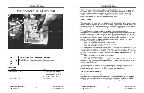
TRANSFORMER TEST – SECONDARY VOLTAGE<br />
LEGEND HEATERS<br />
SERVICE WORKBOOK<br />
single trial version with an alarm contact. Any failure that is sensed by a component in<br />
the safety circuit or the gas valve position indicating switches will cause the boiler to<br />
simultaneously shut down the gas valves while opening the vent valve, purge the<br />
combustion chamber, continuously sound the alarm and lock out. The power to the<br />
ignition module must be manually reset to restart the boiler.<br />
INSTALLATION<br />
The gas control train has a main manual gas shutoff valve installed at the factory. A gas<br />
service pressure regulator is required to maintain a gas supply pressure below the<br />
maximum allowable pressure indicated on the appliance rating plate. A dirt leg shall be<br />
provided in the gas piping per the National Fuel Gas Code (NFPA 54).<br />
S<br />
T<br />
E<br />
P<br />
RESULTS<br />
Transformer Test – Secondary Voltage<br />
3<br />
Test for 24 VAC between the two transformer terminals.<br />
If the meter:<br />
then<br />
does not read 24 VAC<br />
• check 120 VAC supply<br />
connection to primary side<br />
of transformer. (Step 1)<br />
• replace transformer.<br />
does read 24 VAC go to step 4.<br />
Vent lines from gas regulators, switches, and any other equipment requiring<br />
atmospheric pressure to balance a control diaphragm can be manifolded together. The<br />
manifolded line should have a diameter not less than the largest vent line plus 50 % of<br />
the area of the additional vent lines. For example, if the largest vent line is 1/4 inch and<br />
the vent line from the safety switch is 1/8 inch, the manifolded line should be 5/16 inch<br />
minimum. These vent lines should not be manifolded to the following: Vent lines<br />
between the two safety shut-off valves.<br />
Vent lines from the pressure relief valve if provided.<br />
Vent lines from the ignition or main burner systems.<br />
Vent lines from other boilers.<br />
Vent lines between the two safety shut-off valves on the individual burner lines and the<br />
vent lines from the pressure relief valve, if provided, can be manifolded together. The<br />
diameter of the manifolded line must not be less than the largest vent line plus 50% of<br />
the area of the additional vent lines. These vent lines should not be manifolded to the<br />
following:<br />
Vent lines from ignition or main burner systems.<br />
Vent lines from other boilers.<br />
A permanent means for making periodic tightness tests of the safety shut-off valves is<br />
provided for with the appropriate leak test valves located on the downstream side of<br />
each safety shut-off valve.<br />
The boiler shall not be released for operation before the installation, checkout and<br />
start-up has been performed according to the installation, operation and maintenance<br />
manual, the LEGEND 2000 start- up procedures and this insert sheet.<br />
TESTING AND MAINTENANCE<br />
The effective operation of all safety and control devices depends upon their ability to<br />
respond to their activating impulses, therefore it is important that they remain in proper<br />
operating condition at all times. An inspection and maintenance schedule should be<br />
established and performed on a periodic basis. During initial operation, more frequent<br />
A.O. <strong>Smith</strong> <strong>Water</strong> Products Co.<br />
Irving, Texas © 1997<br />
22<br />
Service Workbook<br />
Training Department<br />
A.O. <strong>Smith</strong> <strong>Water</strong> Products Co.<br />
Irving, Texas © 1997<br />
59<br />
Service Workbook<br />
Training Department


