


You also want an ePaper? Increase the reach of your titles
YUMPU automatically turns print PDFs into web optimized ePapers that Google loves.
LEGEND HEATERS<br />
SERVICE WORKBOOK<br />
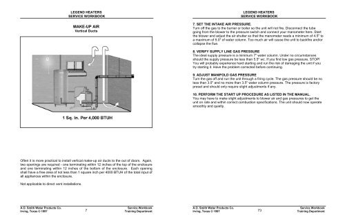
MAKE-UP AIR<br />
Vertical Ducts<br />
LEGEND HEATERS<br />
SERVICE WORKBOOK<br />
7. SET THE INTAKE AIR PRESSURE.<br />
Turn off the gas to the burner or boiler so the unit will not fire. Disconnect the tube<br />
going from the blower to the pressure switch and connect your manometer here. Start<br />
the blower and adjust the air shutter so that the manometer reads a minimum of 4.5" to<br />
a maximum of 5.0" of water column. Too much air will cause the unit to backfire and/or<br />
collapse the flue.<br />
8. VERIFY SUPPLY LINE GAS PRESSURE<br />
The ideal supply pressure is a minimum 7" water column. Under no circumstances<br />
should the supply pressure be less than 5.5" wc. If you find low gas pressure, STOP!<br />
You will probably experience hard starting and run the risk of damaging the unit if you<br />
try starting it. Have the problem corrected before continuing.<br />
9. ADJUST MANIFOLD GAS PRESSURE<br />
Turn the gas off and run the unit through a firing cycle. The gas pressure should be no<br />
less than 3.0" and no more than 3.5" water column pressure. The pressure is factory<br />
preset and should only require slight adjustments if any.<br />
10. PERFORM THE START UP PROCEDURE AS LISTED IN THE MANUAL.<br />
You may have to make slight adjustments to blower air and gas pressures to get the<br />
unit on rate and within correct combustion specifications. The unit should now operate<br />
smoothly and quietly.<br />
Often it is more practical to install vertical make-up air ducts to the out of doors. Again,<br />
two openings are required - one terminating within 12 inches of the top of the enclosure<br />
and one terminating within 12 inches of the bottom of the enclosure. Each opening<br />
shall have a free area of not less than 1 square inch per 4000 BTUH of the total input of<br />
all appliances within the enclosure.<br />
Not applicable to direct vent installations.<br />
A.O. <strong>Smith</strong> <strong>Water</strong> Products Co.<br />
Irving, Texas © 1997<br />
7<br />
Service Workbook<br />
Training Department<br />
A.O. <strong>Smith</strong> <strong>Water</strong> Products Co.<br />
Irving, Texas © 1997<br />
73<br />
Service Workbook<br />
Training Department


