


Create successful ePaper yourself
Turn your PDF publications into a flip-book with our unique Google optimized e-Paper software.
LEGEND HEATERS<br />
SERVICE WORKBOOK<br />
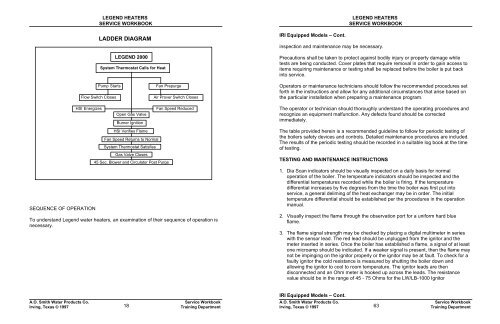
LADDER DIAGRAM<br />
LEGEND 2000<br />
System Thermostat Calls for Heat<br />
Heat<br />
IRI Equipped Models – Cont.<br />
LEGEND HEATERS<br />
SERVICE WORKBOOK<br />
inspection and maintenance may be necessary.<br />
Precautions shall be taken to protect against bodily injury or property damage while<br />
tests are being conducted. Cover plates that require removal in order to gain access to<br />
items requiring maintenance or testing shall be replaced before the boiler is put back<br />
into service.<br />
Pump Starts<br />
Flow Switch Closes<br />
Fan Prepurge<br />
Air Prover Switch Closes<br />
Operators or maintenance technicians should follow the recommended procedures set<br />
forth in the instructions and allow for any additional circumstances that arise based on<br />
the particular installation when preparing a maintenance program.<br />
HSI Energizes<br />
SEQUENCE OF OPERATION<br />
Open Gas Valve<br />
Burner Ignition<br />
HSI Verifies Flame<br />
Fan Speed Returns to Normal<br />
System Thermostat Satisfies<br />
Gas Valve Closes<br />
45 Sec. Blower and Circulator Post Purge<br />
Fan Speed Reduced<br />
Blows<br />
To understand Legend water heaters, an examination of their sequence of operation is<br />
necessary.<br />
The operator or technician should thoroughly understand the operating procedures and<br />
recognize an equipment malfunction. Any defects found should be corrected<br />
immediately.<br />
The table provided herein is a recommended guideline to follow for periodic testing of<br />
the boilers safety devices and controls. Detailed maintenance procedures are included.<br />
The results of the periodic testing should be recorded in a suitable log book at the time<br />
of testing.<br />
TESTING AND MAINTENANCE INSTRUCTIONS<br />
1. Dia Scan indicators should be visually inspected on a daily basis for normal<br />
operation of the boiler. The temperature indicators should be inspected and the<br />
differential temperatures recorded while the boiler is firing. If the temperature<br />
differential increases by five degrees from the time the boiler was first put into<br />
service, a general deliming of the heat exchanger may be in order. The initial<br />
temperature differential should be established per the procedures in the operation<br />
manual.<br />
2. Visually inspect the flame through the observation port for a uniform hard blue<br />
flame.<br />
3. The flame signal strength may be checked by placing a digital multimeter in series<br />
with the sensor lead. The red lead should be unplugged from the ignitor and the<br />
meter inserted in series. Once the boiler has established a flame, a signal of at least<br />
one microamp should be indicated. If a weaker signal is present, then the flame may<br />
not be impinging on the ignitor properly or the ignitor may be at fault. To check for a<br />
faulty ignitor the cold resistance is measured by shutting the boiler down and<br />
allowing the ignitor to cool to room temperature. The ignitor leads are then<br />
disconnected and an Ohm meter is hooked up across the leads. The resistance<br />
value should be in the range of 45 - 75 Ohms for the LW/LB-1000 Ignitor<br />
IRI Equipped Models – Cont.<br />
A.O. <strong>Smith</strong> <strong>Water</strong> Products Co.<br />
Irving, Texas © 1997<br />
18<br />
Service Workbook<br />
Training Department<br />
A.O. <strong>Smith</strong> <strong>Water</strong> Products Co.<br />
Irving, Texas © 1997<br />
63<br />
Service Workbook<br />
Training Department


