Performance
Performance
Performance
- No tags were found...

Create successful ePaper yourself
Turn your PDF publications into a flip-book with our unique Google optimized e-Paper software.
Bristol 0117 923 2523 Manchester 0161 480 6402 TECHNICAL ADVICE 05<br />
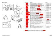
Camshafts<br />
Camshaft Fitting Instructions<br />
The installation and first few moments of running are critical factors in the life of the camshaft.<br />
Failure to install the camshaft correctly will have a drastic effect on the life of the camshaft and in<br />
the worst cases can result in immediate failure. The following instructions must be adhered to in<br />
order to obtain maximum performance from the engine and to ensure a long and trouble free life<br />
from both camshaft and associated components. These instructions are also provided in addition<br />
to the original manufacturer’s installation procedure.<br />
Where a camshaft is being replaced due to excessive wear, it would be highly recommended to strip<br />
the engine and fully clean the internals. Metal particles present in the sump, oil pump, bearings and<br />
oil galleries will soon play havoc with the new cam. It would also be wise to check the oil feed<br />
system. Low oil pressure due to a worn pump, blocked pick-up pipe or blocked oil galleries will<br />
quickly wear the new cam to the same state as the one being replaced. In other words, before<br />
replacing a failed camshaft, make sure you find out the reasons for the failure and correct it!<br />
manufacturing tolerances of cylinder heads, all springs should be checked and<br />
measured for clearance.<br />
2. Coil binding does not exist at full valve lift. This is the condition where the spring is<br />
fully compressed. As a guide, the spring should be able to compress a further 0.060”<br />
(1.5mm) before the coil bound condition is reached. This can be checked by inserting<br />
feeler gauges between each coil of the spring and adding the results together to get<br />
a total clearance figure. Due to varying manufacturing tolerances of cylinder heads,<br />
all springs should be checked and measured for clearance.<br />
Check the clearance between the bottom face of each retainer and the top of the guide or stem<br />
seal at full lift. This should be a minimum of 0.080” (2mm). If this clearance cannot be achieved,<br />
the top of the guides must be machined. When double valve springs are being installed in place of<br />
singles, ensure the inner spring is correctly located and the correct retainers and platforms are<br />
used where applicable. When modifying engines that utilise finger followers, it is imperative that<br />
you ensure the followers remain in the original attitude relative to the cylinder head. Failure to do<br />
so will alter the rocker geometry, increasing or decreasing valve lift and can result in failure of both<br />
cam and followers or excessive valve stem/guide wear. For OHV engines, attention should be paid<br />
to rocker arm geometry for the same reasons.<br />
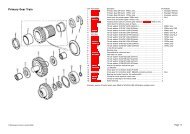
Camshaft Timing<br />
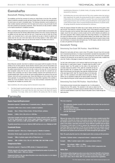
Determining True Crank TDC Position - Head Off Block<br />
Although the crank pulley will have a mark to show TDC position, this point may not be accurate<br />
due to manufacturing tolerances. It is always recommended to calculate the actual position of TDC<br />
rather than rely on the mark on the crank pulley. Fit the timing disc to the front of the crankshaft.<br />
A pointer for the timing disc can be made from a piece of bent wire secured under a suitable front<br />
cover bolt. Position a dial gauge to measure the travel of No 1 piston.<br />
Before fitting the camshaft, check that it is identical in every aspect (with the exception of the lobe<br />
profiles) to the one being replaced. Special attention should be given to the oil feed positions and<br />
journal diameters as variations may occur during the manufacture of the engine. Also check that<br />
any gallery bungs present on the old cam are also in place on the new cam. Do not remove the<br />
black phosphate coating from the new cam lobes. Liberally coat both the camshaft and cam<br />
followers with a proprietary cam lube or engine assembly compound. We recommend and use a<br />
colloidal graphite paste. Failure to do this can cause scuffing between the surfaces of the cam and<br />
followers, which will result in premature wear. Ensure that followers are free to rotate in their bores<br />
where applicable. It is essential that new followers are always fitted, regardless of the condition or<br />
limited use of the old followers. Failure to do so may cause premature components failure and<br />
consequently will invalidate any warranty claim.<br />
Upon installation, the valve springs must be checked to ensure that:<br />
1. The fitted length (installed height) of the valve springs match the figure provided by<br />
the manufacturer. If too small, then the valve seat areas in the head will require<br />
machining. If too large, shims can be added to the spring seat. Due to varying<br />
Formula<br />
Engine Capacity/Displacement<br />
Information required: 1. Cylinder bore, 2. Crankshaft stroke, 3. Number of cylinders.<br />
Calculation: 0.7854 x bore x bore x stroke x number of cylinders.<br />
Example:<br />
Solution:<br />
Bore = 73.5mm (7.35cm), Stroke = 81.3mm (8.13cm), cylinders.<br />
0.7854 x 7.35 x 7.35 x 8.13 x 4 = 1379.79cc.<br />
In the above example we have used centimetres to calculate capacity in cubic centimetres.<br />
To find the displacement in cubic inches simply substitute measurements in inches:<br />
7.35cm = 2.893” and 8.13cm = 3.200” giving 0.7854 x 2.893” x 2.893” x 3.200”x 4 = 84.13 cu.in.<br />
To quickly convert from cc’s to cu.ins. divide by 16.387 and from cu.in. to cc. Multiply by 16.387.<br />
Crankshaft Stroke<br />
Information required: 1. Bore size, 2. Engine capacity, 3. Number of cylinders.<br />
Calculation: Divide engine capacity by: (0.7854 x bore x bore x no. of cylinders).<br />
Turn the crank until the piston is at its maximum height and zero the gauge. You will<br />
find that there is a dwell period of approx. 10 degrees where the piston is at its<br />
maximum height. True TDC position is at the centre of this dwell period. To<br />
accurately measure the position of TDC, rotate the crankshaft and stop at a<br />
figure just before TDC, for example 0.020” on the dial gauge. Record the<br />
figure on the timing disc from the pointer. Now rotate the crankshaft and stop<br />
at the same figure (0.020”) after TDC. Record the figure on the timing disc<br />
again. True TDC is positioned in the middle of these two figures. The TDC<br />
position can be calculated by adding the two figures together and dividing<br />
by two. Adjust the timing disc so that it reads zero on the pointer at true TDC.<br />
Determining True Crank TDC Position - Head On Block<br />
If the head has not been removed when changing the cam, it is still possible to<br />
measure the true TDC position. The procedure is the same as above but the<br />
movement of the piston is recorded by using an extension resting on the piston crown<br />
(such as a socket extension or push rod). Access to the piston crown is made through the<br />
spark plug hole.<br />
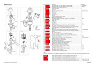
This area comprises:<br />
1. The combustion chamber (usually in the cylinder head as shown, but can also be in<br />
the piston crown).<br />
2. The head gasket thickness.<br />
3. The area between the cylinder block face and the piston crown, commonly referred<br />
to as the ‘deck height’.<br />
Procedure:<br />
Measure the volume of the cylinder and/or piston chambers using a suitable burette filled<br />
with paraffin. Calculate the volume of the gasket and deck height areas and add these to<br />
the chamber volume to arrive at the total compressed volume. Some engines with irregular<br />
piston crown shapes, especially raised areas, may be difficult to quantify with any degree<br />
of accuracy. In such cases it is best to measure the compressed area with the cylinder<br />
head fitted. Make sure the piston is at TDC and seal the gap between the cylinder wall and<br />
the piston with grease (this will prevent seepage past the rings giving a false reading).<br />
Refit gasket and cylinder head and measure the volume through the spark plug hole.<br />
Note: The spark plug hole must be at the highest point when carrying out this procedure.<br />
Example:<br />
1380cc 4 cylinder engine with an 73.5mm bore size.<br />
Calculation: (Cylinder volume + compressed volume) ÷ compressed volume.<br />
Solution: 1380 ÷ (0.7854 x 7.35 x 7.35 x 4) = 169.717086, 1380 ÷169.717086 = 8.13cm.<br />
Compression Ratio<br />
Information required: 1. Capacity of ONE cylinder, 2. Compressed volume.<br />
Cylinder capacity is the total engine displacement divided by the number of cylinders. E.g:<br />
4 cylinder 1000cc engine = 250cc per cylinder.<br />
Compressed volume is the area above the piston crown when the piston is at its highest<br />
point or top dead centre (TDC).<br />
Example:<br />
Solution:<br />
Valve Size<br />
1000cc 4 cylinder engine with a compressed volume of 27cc’s.<br />
One cylinder = 1000cc ÷ 4 = 250cc.<br />
(250cc + 27cc) ÷ 27cc = 277cc ÷ 27 = 10.26 or 10.26:1 compression ratio.<br />
The maximum airflow through any valve occurs when it has been lifted 25% of its diameter.<br />
For example, a 37mm (1.45”) valve will require a lift of no more than 9.25mm (.364”) and a<br />
31mm (1.22”) valve a lift of 7.75mm (.305”) to reach their maximum flow capabilities.<br />
For the latest prices, please visit www.moss-europe.co.uk