Performance
Performance
Performance
- No tags were found...

You also want an ePaper? Increase the reach of your titles
YUMPU automatically turns print PDFs into web optimized ePapers that Google loves.
06 TECHNICAL ADVICE www.moss-europe.co.uk London 020 8867 2020 Bradford 01274 539 999<br />
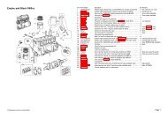
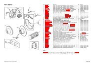
Timing In The Camshaft<br />
Rotate the crankshaft clockwise to 90 degrees after TDC. This will make sure all the pistons are half<br />
way down the bore. Now position the dial gauge so that it can read the lift of the inlet valve of<br />
number 1 cylinder from the top of the valve retainer. Rotate the cam until the gauge shows that the<br />
valve is at full lift. As with the crankshaft, there will be a dwell period where the valve is at full lift.<br />
True full lift is at the centre of this dwell period. Roughly position the cam at true lift position.<br />
Now rotate the crankshaft clockwise to the full valve lift position (as specified on the camshaft data<br />
sheet - this figure is typically from 100 to 120 degrees after TDC), fit the timing belt or chain and<br />
set up the tensioner. Now rotate the crank clockwise until the inlet valve of number one cylinder is<br />
just off full lift position (such as 0.005” or 0.15mm). Record the figure on the timing disc from the<br />
pointer. Then continue to rotate the crank clockwise until the valve has fully opened and then closed<br />
by the same distance as previously used (0.005” or 0.15mm). Read the figure on the timing disc<br />
again. The position of full lift is the middle of these two figures. The full lift position can be calculated<br />
by adding the two figures together and dividing by two. Adjustments can then be made to the<br />
camshaft timing, using an adjustable cam pulley or offset dowels, if this figure does not agree with<br />
the one on the data sheet. Check the timing again after adjustments using the same procedure.<br />
Having timed the camshaft, check that there is no piston to valve contact. Minimum clearance is<br />
0.060” (1.5mm). This can only be checked by dummy building the engine with a piece of plasticine<br />
placed on the crown of the piston. As the engine is turned, the valves will indent the plasticine. The<br />
clearance is then measured as the thickness of the plasticine between the piston crown to the bottom<br />
of the valve indent. Before starting the engine, turn the engine over by hand to ensure that it turns<br />
freely. Prime the oil system and check that everything is set to ensure that the engine starts straight<br />
away. The engine must not be turned over for any length of time on the starter. Once started, do not<br />
allow the engine to idle for the first 20 minutes and keep the revs to a minimum of 2500 rpm. This<br />
will ensure adequate lubrication of the cam and followers and reduce the contact force between the<br />
cam and follower. If any adjustments need to be made within the first 20 minutes, then shut the<br />
engine down. DO NOT ALLOW THE ENGINE TO IDLE. Please note that new hydraulic lifters may in<br />
some cases operate with excessive noise for a few minutes before they are fully charged with oil.<br />
<strong>Performance</strong> Camshafts<br />
All the Kent camshaft applications/part numbers below with the suffix ‘P’ are for the original pin<br />
drive oil pump/ camshaft. If you have changed your camshaft and oil pump to either ‘Star’ drive or<br />
‘Metro Slot’, use the suffix ‘S’ or ‘M’ on the part number. All Piper cams with the suffix E are Star<br />
Drive unless otherwise stated.<br />
To assist in selecting a suitable camshaft we have prepared a table showing their various<br />
characteristics, these will change from engine to engine and with other modifications such as<br />
carburettor or valve size. A scatter profile is where the cam timing on No.2 and 3 engine cylinders<br />
has been altered slightly to combat the poor scavenging of the siamese port design. This will<br />
benefit both the tickover and high end performance.<br />
The effect of a larger engine is to lower the camshaft’s power range slightly. Care must be taken to<br />
ensure that installation is carried out correctly and that components all work together or you will not<br />
get the expected power output or reliability. It is essential that the new cam is fitted with new<br />
followers as they mate with the lobe that they run on and should never be used on another lobe.<br />
Lightened and Tuftrided followers wear more slowly and put less load on high lift cam lobes: They<br />
are also manufactured with a drainage hole. Another essential is the special lubricant that must be<br />
used with all new cams, it provides vital lubrication during initial starting and protects your cam from<br />
extreme wear in its first minute of use. (S/T = Special Tuning) Don’t forget the camshaft assembly<br />
lubricant or the cam timing degree disc (TT2929), you will need this to set your cam timing.<br />
KENT CAMS PART NO. INLET EXHAUST DURATION CAM LIFT DESCRIPTION<br />
CAMSHAFT TYPE<br />
INL - EXH<br />
Road KMD256 21/53 53/21 220-254° 0.263” 998cc Street Cam<br />
Fast Road KMD266 24/56 61/29 260-270° 0.263”-0.270” 1275cc Smooth Idle<br />
Road Rally KMD276 29/61 66/34 270-280° 0.293”-0.315” 1275cc Slightly Lumpy Idle Very Good Street Cam<br />
Rally KMD286 34/66 71/39 280-290° 0.315”-0.324” 1275cc Lumpy Idle Max Street Cam<br />
Rally Scatter KMD286SP 34/66 71/39 280-290° 0.315”-0.324” 1275cc Lumpy Idle Max Street Cam<br />
Race KMD296 39/71 76/44 296-300° 0.324”-0.340” 1275cc Race/1380cc Slightly Lumpy<br />
Race Scatter KMD296SP 39/71 76/44 296-300° 0.324”-0.340” 1275cc Race/1380cc Slightly Lumpy<br />
Full Race Scatter KMD310SP 49/81 81/49 310° 0.340” Full Race<br />
S/T Road STA600S 33/65 63/31 278-274° 0.293” Classic Road Cam<br />
S/T Fast Road/Rally STA731 24/64 59/29 268° 0.263” Classic Fast Road Cam<br />
S/T Fast Road/Rally STA800S 24/64 59/29 268° 0.263” Classic Fast Road Cam<br />
PIPER CAMSHAFT PART NO. INLET EXHAUST DURATION CAM LIFT DESCRIPTION<br />
TYPE<br />
INL - EXH<br />
Fast Road (Stage 2) AHR2702E 39/73 73/39 292° 0.288” 1275cc Fast Road Cam<br />
Fast Road AHR270E 37/71 73/39 288° 0.277” 1275cc Road Cam<br />
Road Rally AHR2852E 39/73 66/32 292-278° 0.299” 1275cc Max Street/1380cc Road Cam<br />
Rally AHR300E 46/74 74/46 300° 0.316” 1380cc Fast Road Cam<br />
Sprint AHR320E 54/82 82/54 316° 0.316” Race<br />
Race 2 AHR3202E 62/86 86/62 328° 0.322” Full Race<br />
ACCESSORIES PART NO. DESCRIPTION<br />
Cam Lube KEN2 250ml Cam Lubricant<br />
Cam Timing Disc TT2929 360° Timing Wheel<br />
Carburettor Jet Selection<br />
This is a quick guide to jet selection for 1275cc Weber carburettors.<br />
Note: Jet selections shown are a basis to work from, they may need adjustment to suit your application, this can only be carried out on a rolling road.<br />
1275cc WEBER CARBURETTOR 40 ROAD 45 FAST ROAD 45 FAST ROAD AND SPRINT 45 RACE<br />
Auxiliary Venturi 3.5 4.5 4.5 4.5<br />
Choke 34 36 38 40<br />
Main Jet 145 150 170 200<br />
Air Cor. 175 180 180 175<br />
Emulsion Tube F2 F2 F2 F2/F9<br />
Pump Jet 45 50 55 55/60<br />
Idle Jet 45F8 50F8 55F8 55F8